Air conditioning installation and control method

A technology for facilities, air conditioners, applied in the direction of space heating and ventilation control input, heating and ventilation control system, control input involving air characteristics, etc., can solve problems such as difficult to cool cabinets

Inactive Publication Date: 2011-01-05
FUJITSU LTD
View PDF17 Cites 4 Cited by
  • Summary
  • Abstract
  • Description
  • Claims
  • Application Information

AI Technical Summary

Problems solved by technology

The technology also makes it difficult to cool the cabinets properly

Method used


Image

  • Air conditioning installation and control method
  • Air conditioning installation and control method
  • Air conditioning installation and control method

Examples


no. 1 approach

[0021] In the following embodiments, the configuration and processing of the air conditioning facility 1 according to the first embodiment will be described, and then the advantages obtained by using the first embodiment will be described.

[0022] Will refer to figure 1 The configuration of the air conditioning facility 1 according to the first embodiment is described. figure 1 The configuration of the air conditioning facility 1 according to the first embodiment is explained.

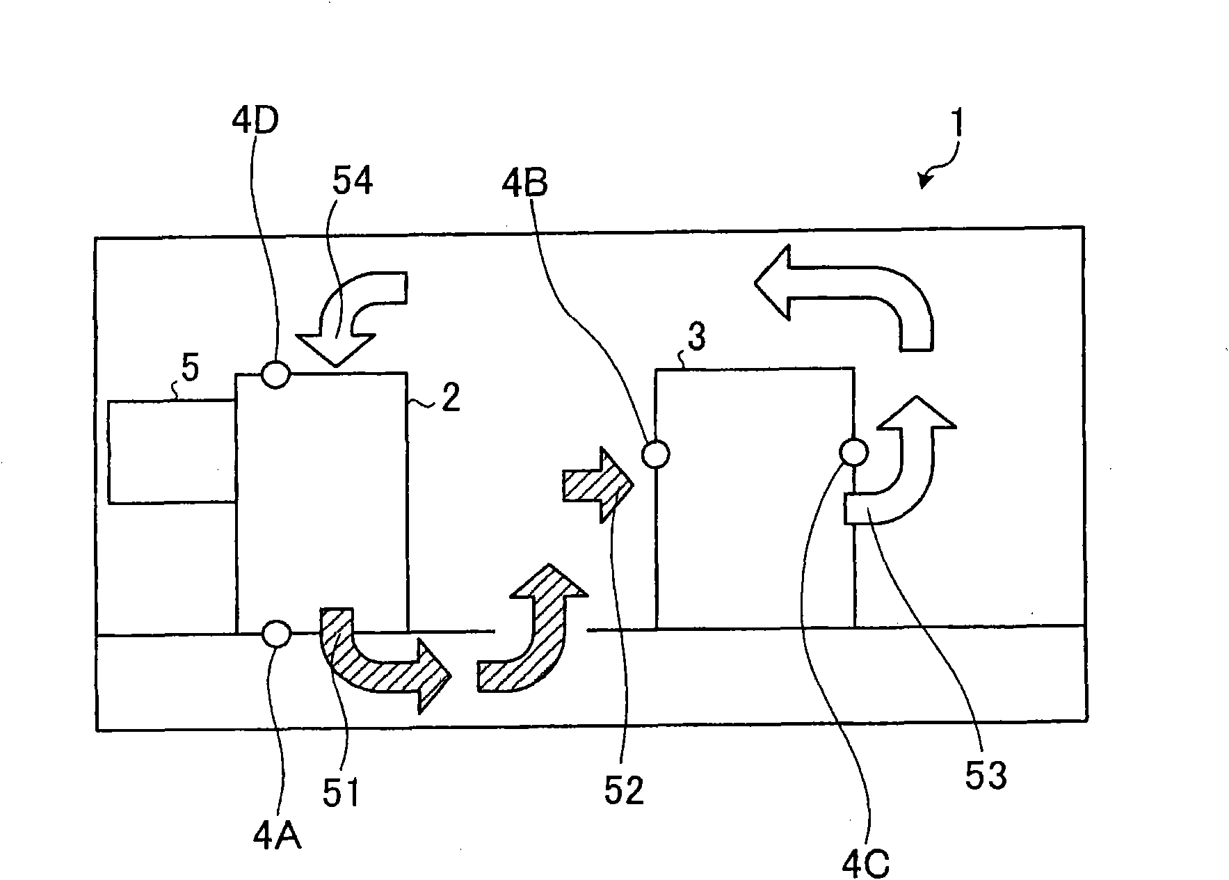
[0023] reference figure 1 The air-conditioning facility 1 of the first embodiment includes an air conditioner 2 that blows cold air to the cabinet 3, a cabinet 3 that receives cold air from the air conditioner 2 and discharges hot air, temperature detectors 4A to 4D that detect temperature, and controls the air conditioner 2 Air volume air volume control unit 5. in figure 1 In the middle, the shaded arrow indicates the flow of cold air, and the white arrow indicates the flow of hot air.

[0024] The air con...

no. 2 approach

[0032] In the following embodiments, the configuration and processing of the air conditioning facility 100 according to the second embodiment will be described, and subsequently, the advantages obtained with the second embodiment will be described.

[0033] [Configuration of Air Conditioning System]

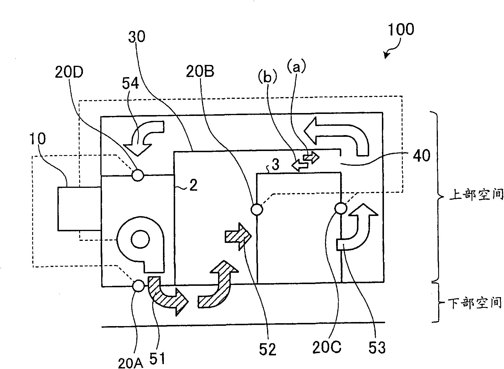
[0034] Will refer to figure 2 The configuration of the air conditioning facility 100 according to the second embodiment is described. figure 2 It is a block diagram of the configuration of the air conditioning facility 100 according to the second embodiment. reference figure 2 The air conditioning facility 100 includes an air conditioner 2, a cabinet 3, an air conditioning control unit 10 as an air volume control unit, temperature detectors 20A to 20D, an exhaust guide path 30, and air holes 40. The air conditioning control unit 10 is connected to the temperature detectors 20A to 20D through a LAN.

[0035] The air conditioning facility 100 has a double-layer structure that provides...


PUM


Abstract

The invention relates to an air conditioning installation and the control method. An installation for cooling an electronic device includes an air conditioner having an air outlet for blowing cooling air to a room; a first detector adjacent to the air outlet of the air conditioner, for detecting a temperature of the cooling air; a rack accommodating the electronic device, the rack having an air inlet for receiving the cooling air from the air conditioner and an air outlet for exhausting air to the room; a second detector adjacent to the air inlet of the rack, for detecting a temperature of air received through the air inlet of the rack; and a controller for acquiring the temperatures detected by the first and the second detectors, and controlling a quantity of the cooling air blown from the air outlet of the air conditioner so as to decrease a difference between the temperatures detected by the first and the second detectors.

Description

Technical field [0001] The embodiments discussed herein relate to air conditioning facilities and air conditioning control methods that control the amount of air from an air conditioner. Background technique [0002] In recent years, cabinets have been installed in spaces called data centers or computer rooms. IT equipment such as servers and network equipment is installed in the cabinet. Since IT equipment includes functional components, such as a CPU, the IT equipment uses electricity and generates heat. The temperature of the IT equipment needs to be maintained at or below a certain temperature to ensure normal operation. Therefore, air conditioning facilities are used. The air conditioning facility cools the IT equipment in the cabinet by blowing cold air from the air conditioner. [0003] The air circulation of the air conditioning facility will be described below. The air conditioner blows cold air to provide cold air to the cabinet. Fans embedded in the IT equipment in...

Claims


Application Information

Patent Timeline
Patent Type & Authority Applications(China)
IPC IPC(8): F24F11/02F24F11/00F24F11/76
CPCF24F11/0001H05K7/20745F24F11/053F24F11/76F24F11/30F24F2110/10H05K7/2059
Inventor 大庭雄次石峰润一永松郁朗铃木正博胜井忠士山冈伸嘉斋藤精一植田晃浦木靖司
Owner FUJITSU LTD
Why Eureka
Try Eureka