Fin type evaporator and refrigerator thereof

A finned evaporator and evaporator technology, applied in evaporators/condensers, defrosting, household appliances, etc., can solve the problems of insufficient support, poor defrosting of heaters, large thermal resistance, etc., to avoid loosening Or falling off, shortening the defrosting time, reducing the effect of heat transfer resistance

Inactive Publication Date: 2011-01-05
HEFEI MIDEA REFRIGERATOR CO LTD +1
View PDF6 Cites 23 Cited by
  • Summary
  • Abstract
  • Description
  • Claims
  • Application Information

AI Technical Summary

Problems solved by technology

In the traditional flat plate structure, the height of the inlet and end of the installation groove is the same, which is equal to or slightly smaller than the diameter of the heater pipe to clamp the heater pipe so that the part of the installation groove in contact with the heater is in linear contact. The heat transfer resistance between the heater and the fins is large, and the large thermal resistance leads to a long defrosting cycle and high energy consumption
At the same time, because the part of the fin installation groove in contact with the heater is in linear contact, the support is not stable enough. After the refrigerator is transported bumpily or after long-term thermal expansion and contraction, the heater in linear contact with the fins may loosen or fall off due to insufficient fixation. possible, the looseness of the heater will cause the problem of poor defrosting
[0008] Moreover, in order to simplify the manufacturing process of the existing evaporator fins, the periphery of the fins is mostly set at right angles or oblique angles, and the protruding fins are easy to scratch the operator when the evaporator is assembled or maintained.
[0009] Moreover, the depth of the existing heater embedded in several fins is very shallow, so that the gap between the outer wall of the heater and the edge of the fins is small, and the heat of the heater is easily transferred to other adjacent components in the refrigerator, resulting in high temperature of other adjacent components. Deform or accelerate the aging of the part

Method used


Image

  • Fin type evaporator and refrigerator thereof
  • Fin type evaporator and refrigerator thereof
  • Fin type evaporator and refrigerator thereof

Examples


Embodiment Construction

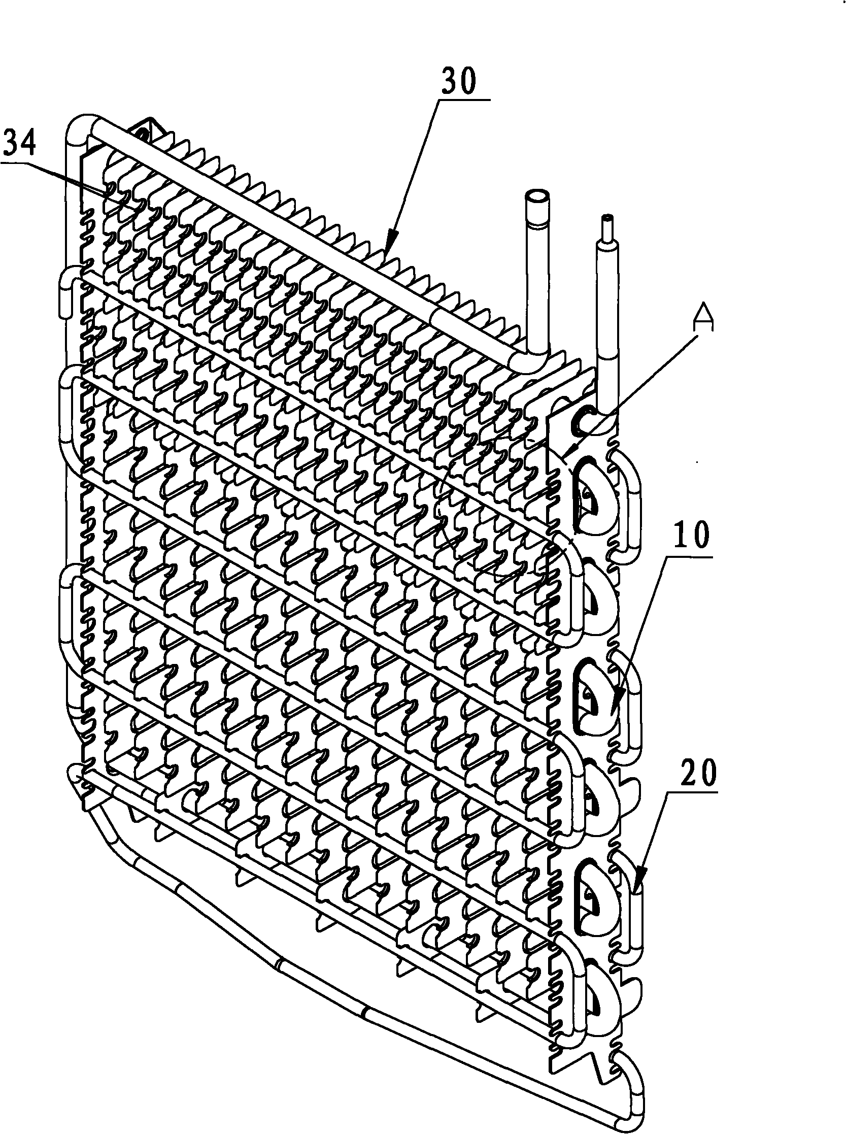
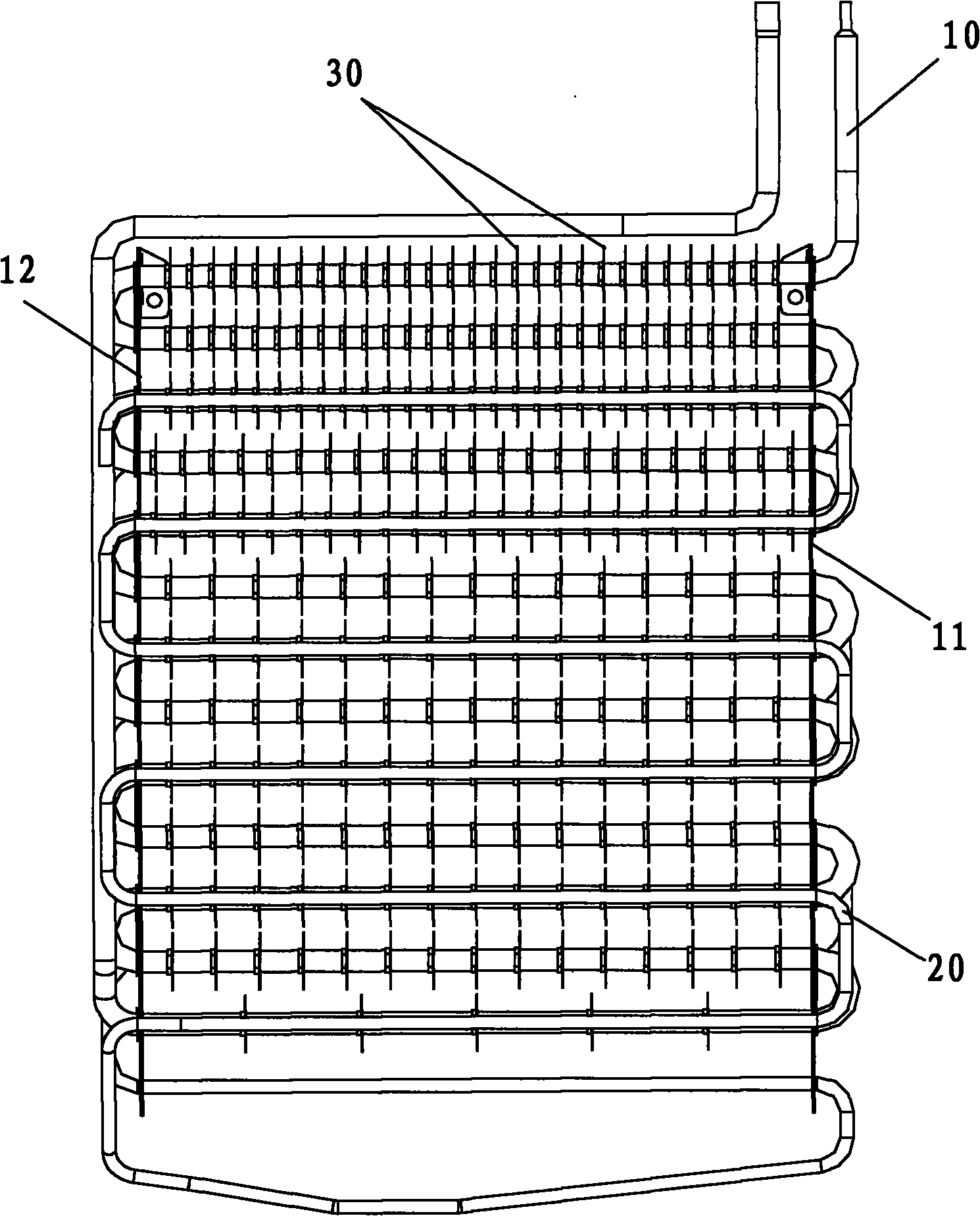
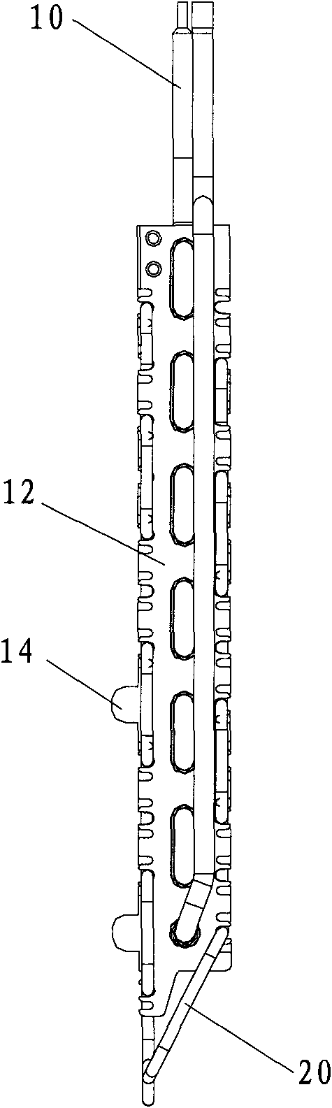
[0035] This embodiment relates to a refrigerator with a novel evaporator, which includes a refrigerator compartment, a freezer compartment and a refrigeration system for the refrigerator. The refrigeration system of the refrigerator includes a compressor for generating cycle power, an evaporator for heat exchange, a capillary tube for expansion, a condenser and a refrigerant flowing in gas-liquid conversion in the piping system. The evaporator is generally installed on the back of the refrigerator. The sensor senses the temperature change of the freezer compartment. When the temperature is lower than the set value, the refrigeration system is activated to cool down. Please refer to figure 1 The evaporator used for heat exchange is the main component of refrigeration, including single or multiple rows of refrigerant coils 10 and several fins 30 sleeved on the refrigerant coils 10 . A groove for installing a heater tube for defrosting is provided on each fin 30 . In this embod...


PUM


Abstract

The invention relates to a fin type evaporator which comprises a fixed plate, single column or multiple columns of refrigerant coil pipes mounted on the fixed plate and a plurality of fins sheathed on the refrigerant coil pipes, wherein a groove is formed on each fin, a heater pipe clamp for defrosting is mounted in each groove, and each fin is provided with a hem for stably clamping a heater pipe along the edge of the groove. The invention further relates to a refrigerator using the evaporator. The fins of the evaporator are provided with the hems for clamping the heater pipes along the edges of the grooves, and the arrangement of the hems change the traditional line contact to the surface contact, thereby reducing the heat transfer resistance between the heater pipes and the fins, shortening the defrosting time, saving the defrosting energy consumption of the evaporator and mounting the heater pipes on the evaporator more firmly.

Description

technical field [0001] The invention relates to a refrigeration system, in particular to a finned evaporator with good heat exchange performance and more excellent defrosting performance in the refrigeration system and a refrigerator thereof. Background technique [0002] A refrigerator refrigeration system generally includes a compressor, an evaporator, a capillary tube for expansion, a condenser, and a refrigerant flowing through gas-liquid conversion in the piping system. Among them, the evaporator is an important part of heat exchange. At present, a large number of air-cooled refrigerators use finned auxetic evaporators, which generally consist of single or multi-row evaporator coils, several fins, fixed plates and heaters. The fins used for heat dissipation and expanding the heat exchange area are arranged on the outer wall of the coil, and there are installation grooves on both sides of the fins of the evaporator, and the defrosting heater is usually fixed in the inst...

Claims


Application Information

Patent Timeline
Patent Type & Authority Applications(China)
IPC IPC(8): F25B39/02F25D21/06
Inventor 方忠诚李凌云任伟
Owner HEFEI MIDEA REFRIGERATOR CO LTD
Why Eureka
Try Eureka