Pneumatic tire for heavy loads

A technology of pneumatic tires and steel cords, which is applied to the reinforcement layers of pneumatic tires, tire parts, vehicle parts, etc., can solve problems such as the reduction of circumferential rigidity, and achieve the effect of achieving durability and improving lightweight effects.

Inactive Publication Date: 2011-01-05
BRIDGESTONE CORP
View PDF2 Cites 5 Cited by
  • Summary
  • Abstract
  • Description
  • Claims
  • Application Information

AI Technical Summary

Problems solved by technology

At the cost of weight reduction, the circumferential rigidity decreases, which becomes a fatal flaw in the performance of heavy-duty pneumatic tires

Method used


Image

  • Pneumatic tire for heavy loads
  • Pneumatic tire for heavy loads
  • Pneumatic tire for heavy loads

Examples


Embodiment

[0041] Hereinafter, the present invention will be described in more detail using examples.

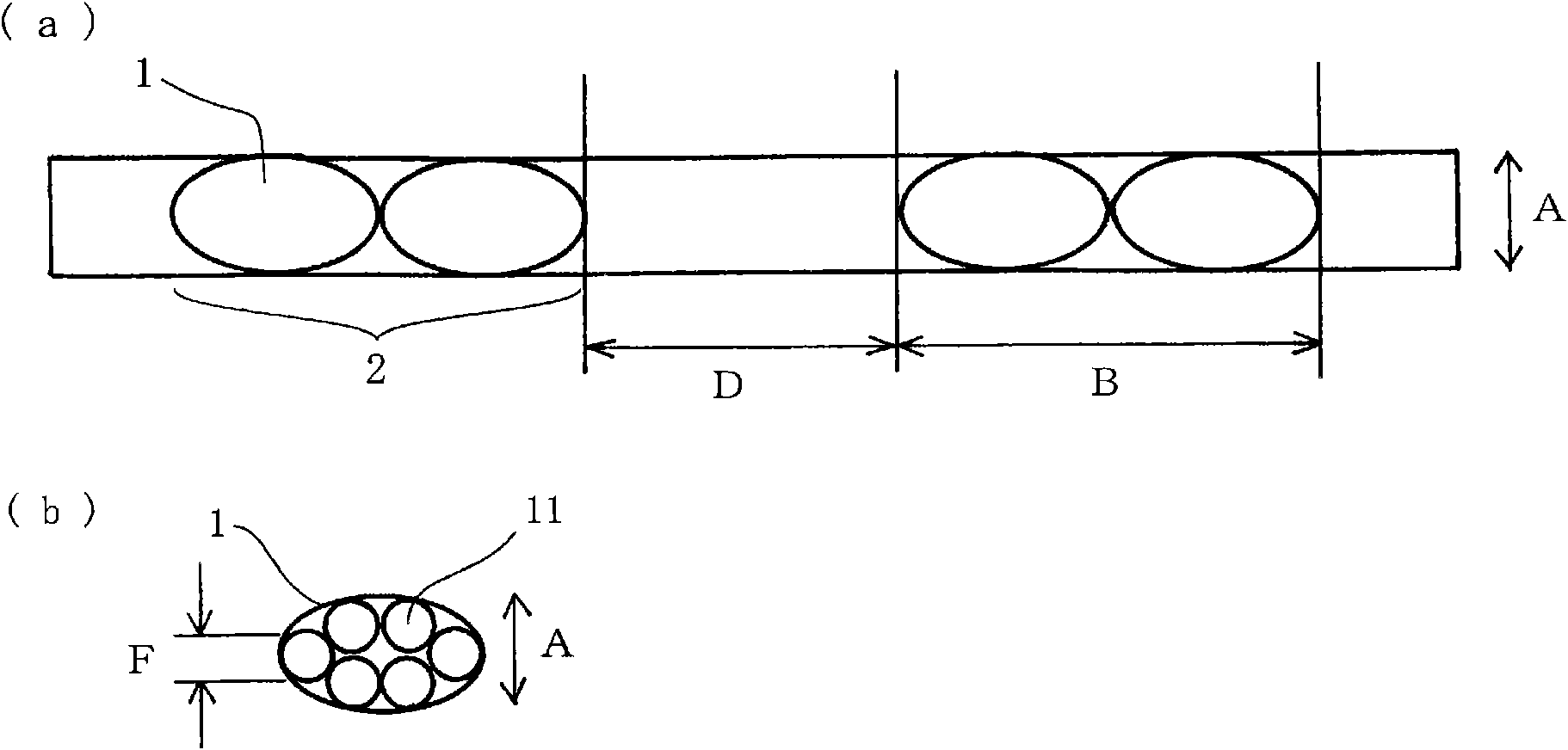
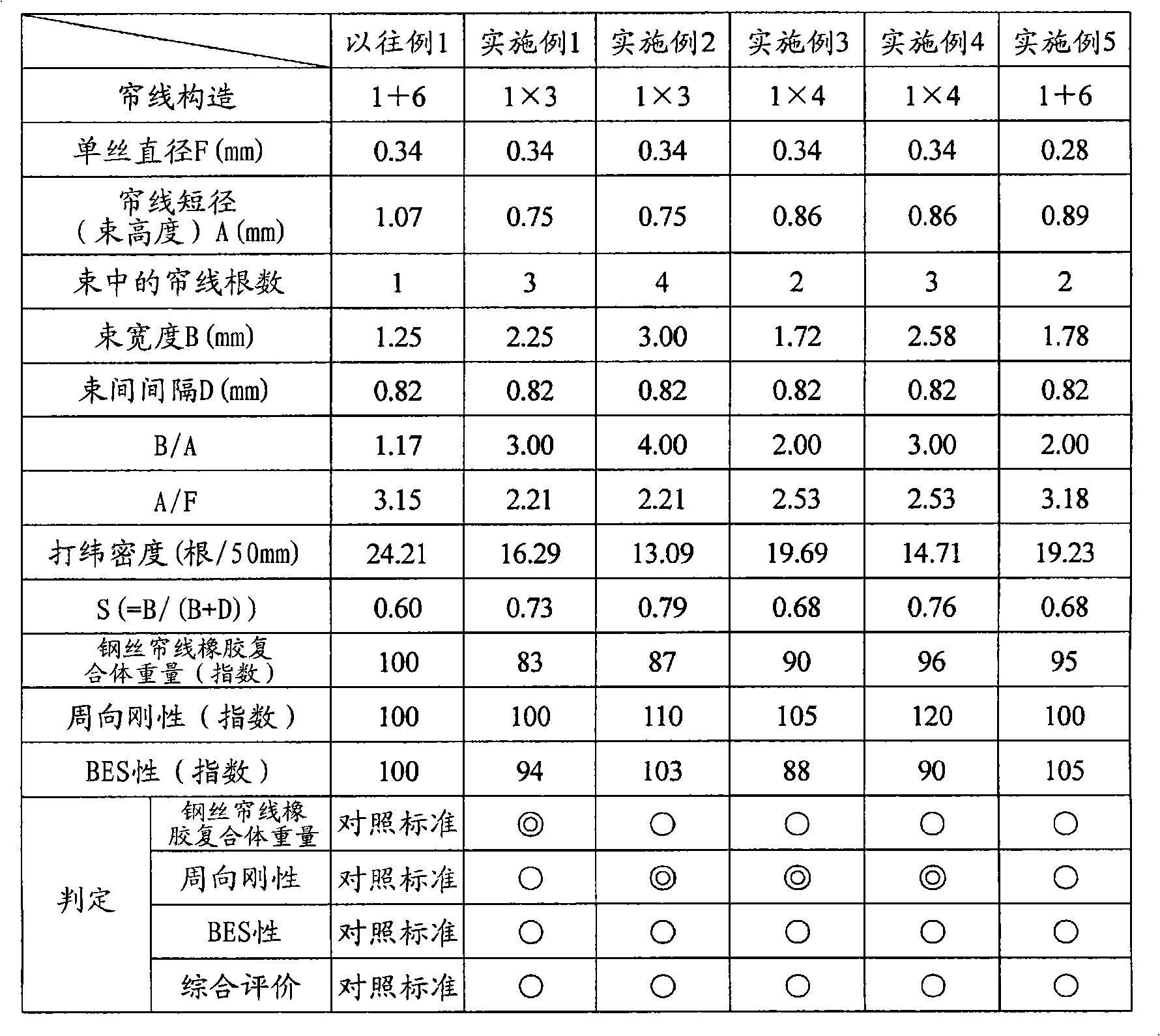
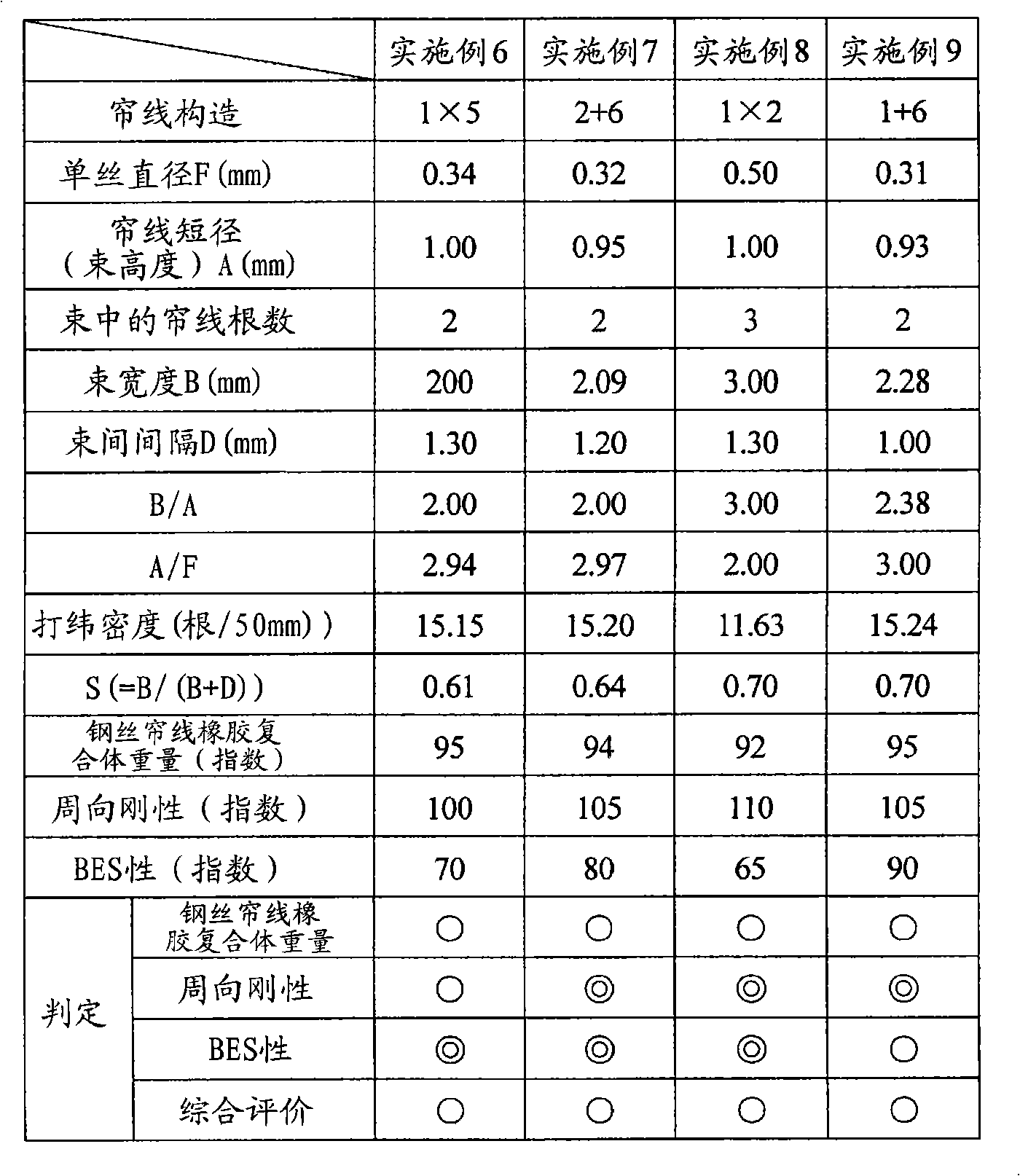
[0042] A bundled cord arrangement according to the conditions in the following table was applied to two main interlaced belt layers among the four-layer steel belt layers to manufacture a heavy-duty pneumatic tire with a tire size of 11R22.5.

[0043] Steel cord rubber compound weight

[0044] For each of the obtained test tires, the steel cord rubber composite weight was determined from the actual measured weight per unit area of ​​the steel cord rubber composite composed of the steel cord and the rubber sheet. The results are shown by an index, where Conventional Example 1 is set to 100. Smaller values ​​mean greater weight reduction effects.

[0045] Circumferential rigidity

[0046] For each of the obtained test tires, the outer circumference of the tire was measured after driving 100,000 km in a field test, and the circumferential rigidity thereof was obtained. Specificall...


PUM


Abstract

Provided is a heavy-load pneumatic tire, which makes both durability and desired circumferential rigidity compatible while saving weight. The heavy-load pneumatic tire includes a steel belt of at least one layer, which is formed such that a plurality of steel cords (1) twisted of a plurality of filaments (11) are arranged in parallel in a bundle state. The height of a cord bundle (2), that is, the shorter diameter (A mm) of the steel cords (1), and a bundle width (B mm) satisfy the following formula (1) of B / A = 2.0 (1). The value of S = B / (B+D), which is defined by the bundle width (B mm) of the cord bundle (2) and a cord-bundle distance (D mm), satisfies the following formula (2) of 0.60 <= S <= 0.80 (2).

Description

technical field [0001] The present invention relates to a heavy-duty pneumatic tire (hereinafter also simply referred to as a "tyre"), and in detail, to a heavy-duty pneumatic tire with an improved steel belt. Background technique [0002] In a steel belt layer of a pneumatic tire for heavy loads, steel cords are usually buried at regular intervals. With regard to the improvement of the steel cords applied to the belt, for example, Patent Document 1 discloses a pneumatic radial tire in which the steel cords of the belt are formed into bundled cords in which N wires are twisted A strand made of a plurality of steel wires is paralleled substantially without twisting and has a flat outline shape. [0003] In addition, for example, Patent Document 2 discloses a pneumatic radial tire in which several reinforcement elements of the belt layer are divided into one bundle, and the scattered interval between the bundle and the reinforcement elements adjacent to the bundle is increase...

Claims


Application Information

Patent Timeline
Patent Type & Authority Applications(China)
IPC IPC(8): B60C9/20B60C9/00B60C9/18D07B1/06
CPCD07B2501/2046D07B1/062D07B2201/2022B60C9/0007D07B2201/2018
Inventor 小山祐司
Owner BRIDGESTONE CORP
Why Eureka
Try Eureka