Oscillating type propeller

A thruster and swing-type technology, which is applied in the direction of non-rotating propulsion elements, non-mechanical gear transmissions, ships, etc., can solve the problems that real-time online adjustment of propellers cannot be realized, and achieve intuitive and simple control operations, and improve Controllability, the effect of reducing self-weight

Inactive Publication Date: 2011-01-12
SHENYANG INST OF AUTOMATION - CHINESE ACAD OF SCI
View PDF0 Cites 4 Cited by
  • Summary
  • Abstract
  • Description
  • Claims
  • Application Information

AI Technical Summary

Problems solved by technology

However, none of them can realize the real-time online adjustment of the propeller to change the installation position and angle of the propeller, thereby improving the maneuverability of the submersible and the ability to capture targets in narrow underwater spaces and multi-obstacle environments

Method used


Image

  • Oscillating type propeller
  • Oscillating type propeller
  • Oscillating type propeller

Examples


Embodiment 1

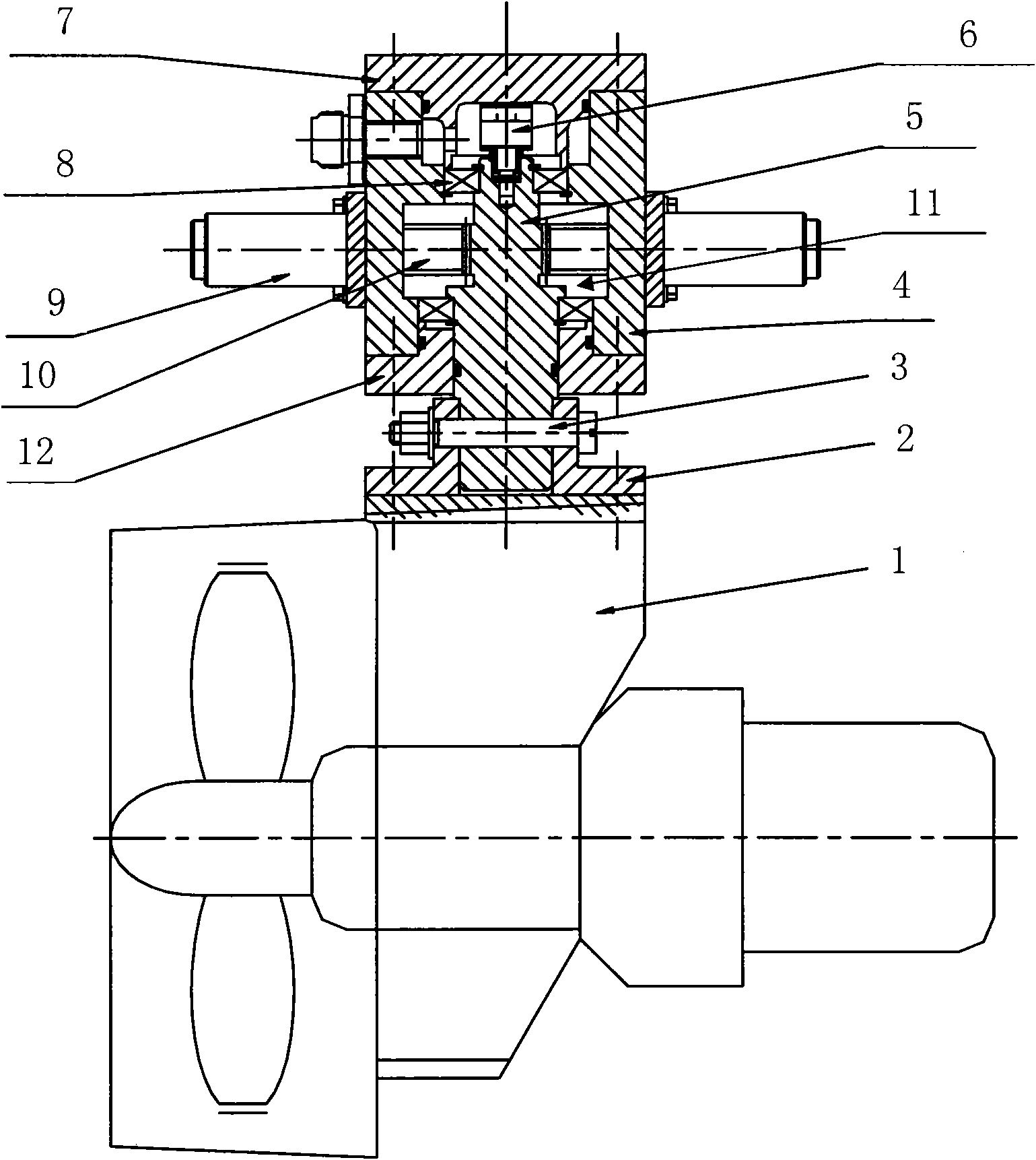
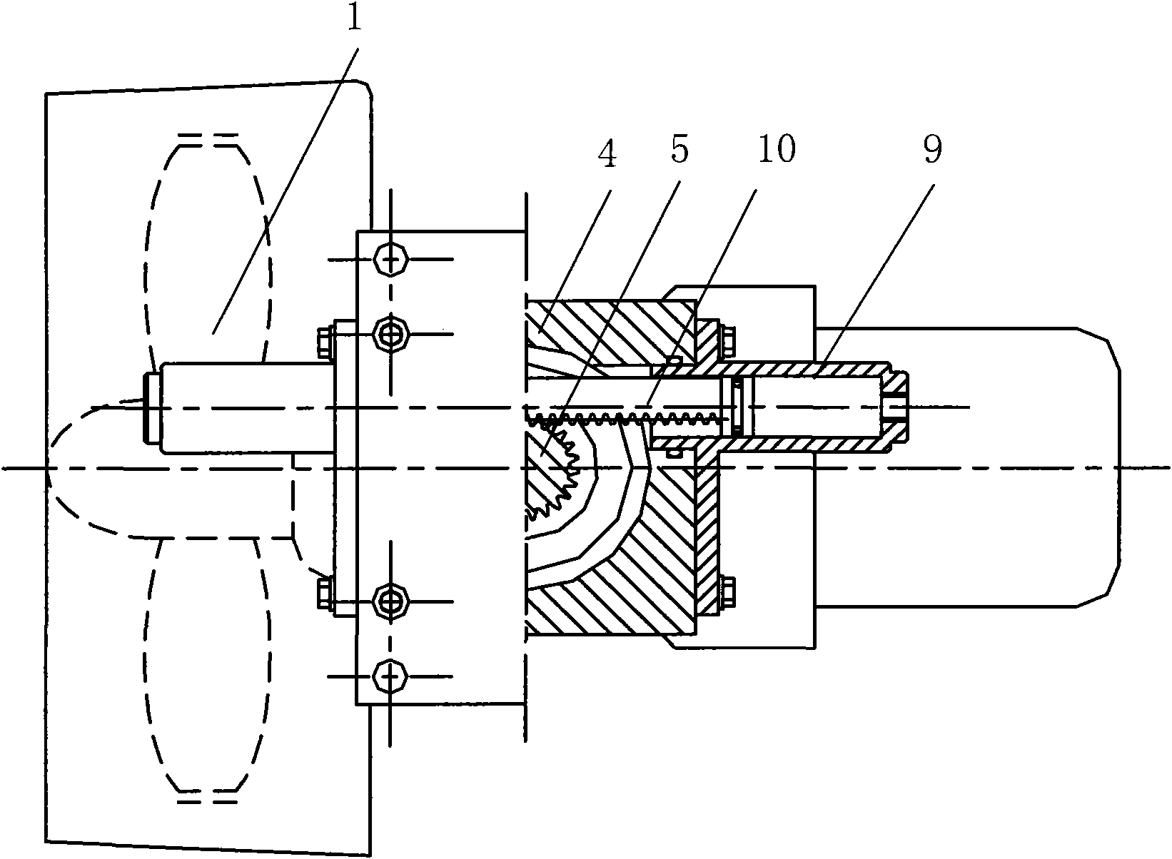
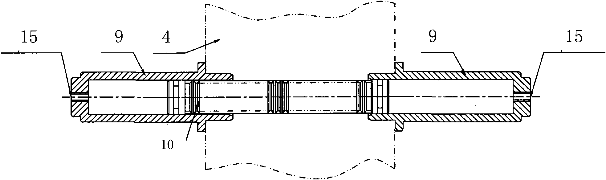
[0017] Embodiment 1: as figure 1 , figure 2 As shown, the present invention comprises propeller 1 and swing mechanism 13, and described swing mechanism 13 is connected with propeller 1 through the swing shaft 5 in it, makes the axis of swing shaft 5 perpendicular to the horizontal axis of propeller 1, and swing shaft The end structure of the propeller 1 connected with 5 matches with the connecting flange 2, and is connected and fixed through the connecting flange 2, and the swing shaft 5 and the connecting flange 2 are connected and fixed through the connecting bolt 3. Described swing mechanism 13 comprises box body 4, swing shaft 5, mounting flange 7, driving mechanism and end cover 12, and box body 4 one end is provided with mounting flange 7, and the other end is equipped with end cover 12, and swing shaft 5 is placed on Inside the box body 4 and extend out the end cover 12, the swing shaft 5 and the box body 4 are installed through the support bearing 8, the installation...

Embodiment 2

[0020] Embodiment 2: The overall structure of this example is the same as that of Embodiment 1, the difference is that: this example installs a gear 14 that matches the driving rack 10 on the swing shaft 5 . The drive rack 10 moves linearly under the push of the hydraulic oil, driving the swing shaft 5 and the propeller 1 to rotate to realize various working states, such as Figure 4 As shown, (a) is a schematic diagram of the front view of the forward and backward state; (b) is a schematic diagram of the front view of the side shift state after (a) is rotated 90 degrees; (c) is a schematic diagram of the top view of the forward and backward state; (d) is ( c) The top view schematic diagram of the heave state after rotating 90 degrees; (e) is the schematic diagram of the propeller rotating an angle A.

[0021] .


PUM


Abstract

The invention relates to an oscillating type propeller which is applicable to an underwater vehicle for an underwater robot. The oscillating type propeller comprises a propeller and an oscillating mechanism, wherein the oscillating mechanism is connected with the propeller by an oscillating shaft arranged in the oscillating mechanism, the oscillating mechanism comprises a case, the oscillating shaft, a mounting flange, a driving mechanism and an end cover, the mounting flange is arranged at one end of the case, the end cover is mounted at the other end of the case, the oscillating shaft is arranged in the case and extends out of the end cover, the driving mechanism is penetrated through the case, is arranged on the case and is connected with the oscillating shaft in the case, the mountingflange and the end cover respectively form tight coupling with the case, the end cover and the oscillating shaft, and a closed cavity is formed in the case. By using the driving mechanism to drive the oscillating shaft to rotate, the invention can realize the free real-time on-line adjustment on the position and the angle of the propeller in the range of the plane perpendicular to the oscillatingshaft +/- 90 degrees, thereby changing the power output characteristics of the underwater vehicle, greatly improving the moving performance controllability and adaptability to complicated underwater environment of the underwater vehicle, and achieving the advantages of simple and reliable application and easy arrangement.

Description

technical field [0001] The invention relates to a swing type propeller, which is suitable for underwater vehicles (submersibles) of underwater robots. Background technique [0002] At present, most of the propellers used on the underwater vehicle (submersible) of the underwater robot are installed in a fixed way; or in order to improve the dynamic performance and controllability of the underwater robot, the propeller is arranged in a way of losing weight. However, none of them can realize the real-time online adjustment of the propeller to change the installation position and angle of the propeller, thereby improving the maneuverability of the submersible and the ability to capture targets in narrow underwater spaces and multi-obstacle environments. Contents of the invention [0003] In view of the above-mentioned technical problems, the object of the present invention is to provide a swing propeller, which can make the propeller swing and rotate to meet various working co...

Claims


Application Information

Patent Timeline
Patent Type & Authority Applications(China)
IPC IPC(8): B63H1/36B63H23/26B63C11/52
Inventor 康守权何立岩
Owner SHENYANG INST OF AUTOMATION - CHINESE ACAD OF SCI
Why Eureka
Try Eureka