
Heavy-load composite function anchoring device for scaffold

A technology of composite function and anchoring device, which is applied in the direction of scaffolding supported by house structure, house structure support, house structure support, etc., can solve the problems of lack of universal adjustment ability, difficulty in continuous operation, and inability to be put into use immediately. Easy installation, stable support, and the effect of reducing the number of

Inactive Publication Date: 2012-02-22
山东高阳建设有限公司 +1
View PDF0 Cites 0 Cited by
  • Summary
  • Abstract
  • Description
  • Claims
  • Application Information

AI Technical Summary

Problems solved by technology

[0002] The anchorage point is used as the load-bearing point. In order to realize the load-bearing, there are many types of anchor rods. The anchor rods used for slope protection have a variety of detachable and reusable anchor rods, but the load capacity is not large; Anchorage point, the fastening point of the pull rope and the consolidation point of the support rod are set on the end surface of the anchor rod. The consolidated state does not have the ability to adjust the universal direction. The heavy-duty anchor point is usually sealed with cement, organic adhesive and other materials. grouting, and the grouting needs solidification time, the construction must be stopped, it cannot be put into use immediately, and it is difficult to realize continuous operation

Method used


Image

  • Heavy-load composite function anchoring device for scaffold
  • Heavy-load composite function anchoring device for scaffold
  • Heavy-load composite function anchoring device for scaffold

Examples


Embodiment Construction

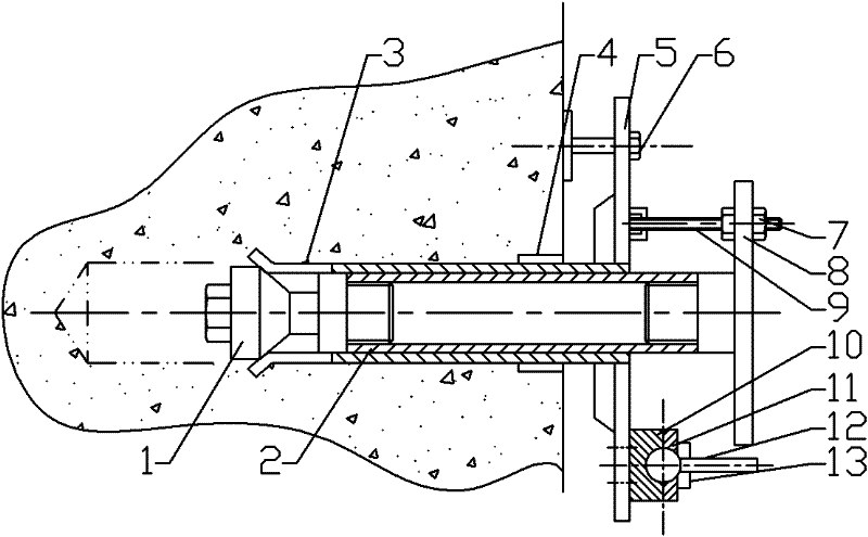
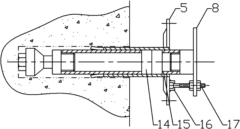
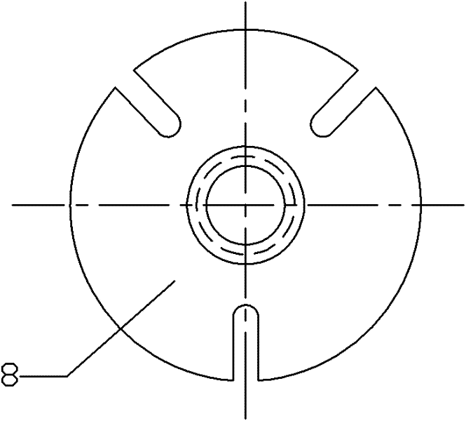
[0014] Refer to attached Figure 1~4 :

[0015] The heavy-duty composite function anchoring device for the scaffold consists of an expansion head 1, an inner tube 2, an outer tube 3, a filling ring 4, an outer tube end plate 5, an anti-loosening bolt 6, a tightening nut 7, and an inner tube end plate 8 , tightening screw 9, turntable base 10, turntable gland 11, turntable shaft 12, turntable stabilizing block 13, dismantling light pad cover 14, dismantling threaded sleeve 15, quick-installing card seat 16 and dismantling screw 17, inner tube 2 Made for heavy-duty seamless pipes, both ends of the pipe body are provided with internal threads, and the upper part is sleeved with an inner pipe end plate 8, and the outer edge of the inner pipe end plate 8 is provided with a plurality of radial short grooves. A tensioning screw 9 and an assembled tensioning nut 7 are installed in the center, the lower part of the inner tube end plate 8 and the upper part of the expansion end 1 are p...


PUM


Abstract

The invention relates to a heavy-load composite function anchoring device for a scaffold, and belongs to the field of construction tools for building plank roads. The heavy-load composite function anchoring device comprises a conical expandable tip (1) and an inner pipe (2), wherein the expandable tip (1) is connected to the lower part of the inner pipe (2). The heavy-load composite function anchoring device is characterized in that an outer thimble (3) is movably sleeved outside the inner pipe (2), a plurality of grooves are formed on the lower part of the outer thimble (3) to form a multi-toothed tip enclosed outside the expandable tip (1), an outer thimble end plate (5) with a reinforcing rib is in sleeve joint with the upper part of the outer thimble (3), a plurality of screw holes and annular lifting lugs for installing safety ropes are formed or arranged on the outer thimble end plate (5), and a plurality of spherical rotary tables are fixed on the outer thimble end plate (5), a filling ring (4) is sleeved outside the outer thimble (3) and in a process gap at the end opening of a down-the-hole, and an inner pipe end plate (8) is arranged on the upper part of the inner pipe (2). The heavy-load composite function anchoring device for the scaffold can be detached and reused, has large bearing capacity, can be fixed in the down-the-hole through mechanical force, has universal adjustment capacity, and needs no shut down.

Description

technical field [0001] The utility model relates to a heavy-load composite function anchoring device for scaffolding, which belongs to the field of building plank road construction tools. Specifically relates to a supporting anchoring device for erecting a working platform on a cliff. Background technique [0002] The anchorage point is used as the load-bearing point. In order to realize the load-bearing, there are many types of anchor rods. The anchor rods used for slope protection have a variety of detachable and reusable anchor rods, but the load capacity is not large; Anchorage point, the fastening point of the pull rope and the consolidation point of the support rod are set on the end surface of the anchor rod. The consolidated state does not have the ability to adjust the universal direction. The heavy-duty anchor point is usually sealed with cement, organic adhesive and other materials. Grouting, and the grouting needs solidification time, the construction must be st...

Claims


Application Information

Patent Timeline
Patent Type & Authority Patents(China)
IPC IPC(8): E02D5/76E04G3/20
Inventor 孙裕国路尚修王德强田绪峰常玉真田昭春赵有光郭海燕许曰祥徐方文常祖奎李明朱栋梁张建王万峰路国兴许连海
Owner 山东高阳建设有限公司
Learn More