
Numerical control proportioning hydraulic directional control valve

A hydraulic reversing valve and proportional technology, applied in the field of hydraulic reversing valve, can solve the problem of not having the functions of precise flow control and pressure control, and achieve the effect of reducing cost and failure rate, simple system and high precision

Inactive Publication Date: 2011-01-12
许新跃
View PDF4 Cites 13 Cited by
  • Summary
  • Abstract
  • Description
  • Claims
  • Application Information

AI Technical Summary

Problems solved by technology

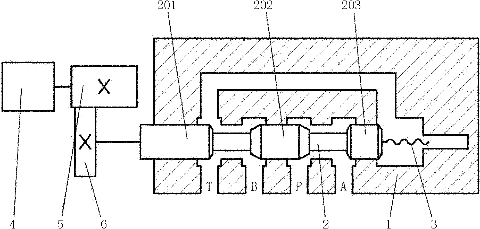
[0003] The present invention aims at the inadequacy of the existing hydraulic reversing valve that does not have the function of precisely controlling the flow and controlling the pressure, and provides a valve that can accurately control the opening of the valve when switching to a certain working oil channel for oil supply. CNC proportional hydraulic directional valve to accurately control flow and pressure

Method used


Image

  • Numerical control proportioning hydraulic directional control valve
  • Numerical control proportioning hydraulic directional control valve
  • Numerical control proportioning hydraulic directional control valve

Examples


Embodiment Construction

[0024] The present invention will be further described through the embodiments below with reference to the accompanying drawings.

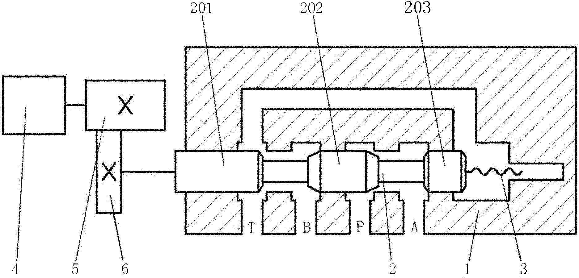
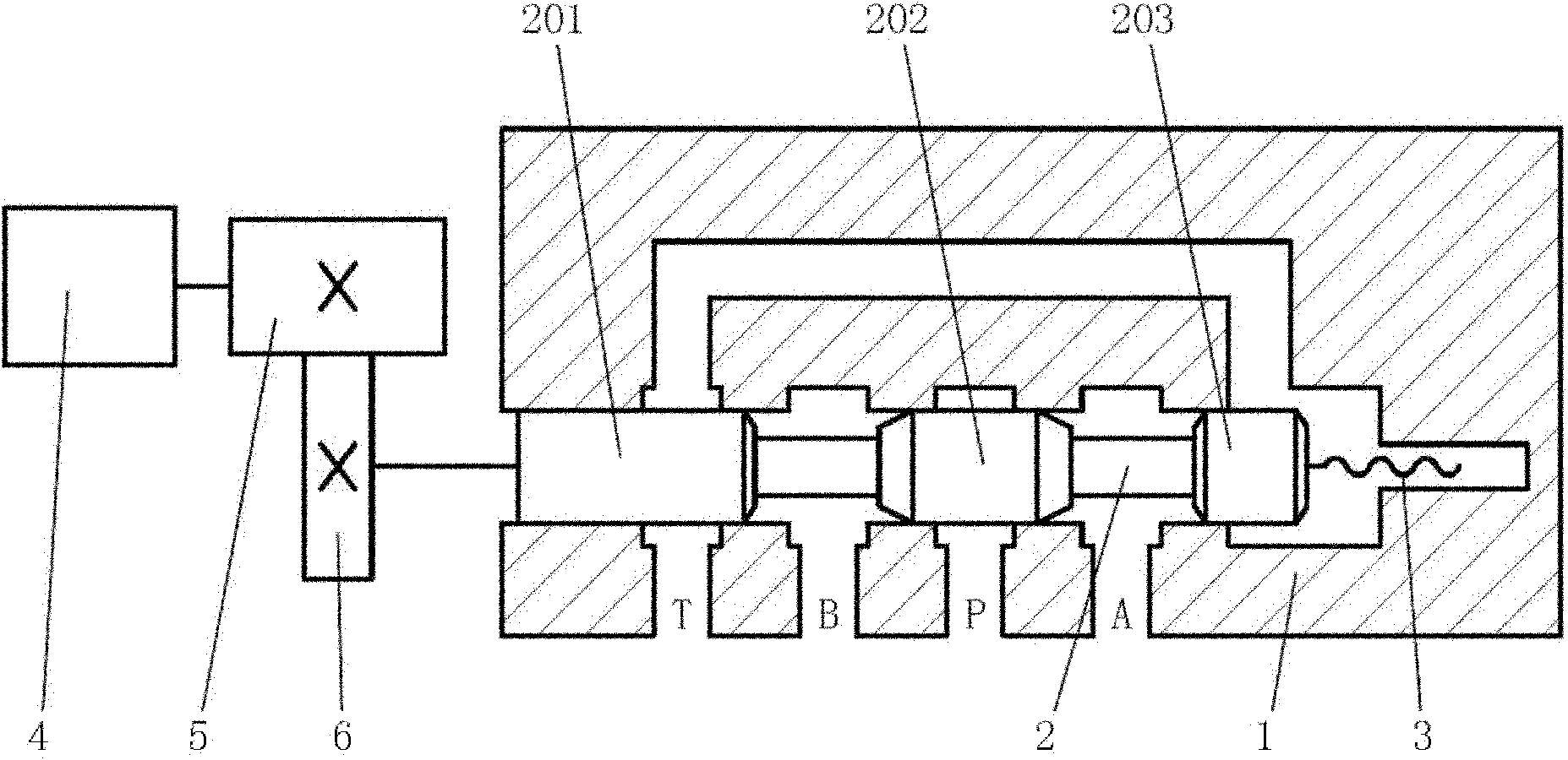
[0025] Refer to attached figure 1 to attach Figure 7 A numerically controlled proportional hydraulic reversing valve includes a valve body 1, a valve core 2, a numerically controlled motor 4 and a transmission mechanism, wherein the numerically controlled motor 4 adopts a stepping motor or a servo motor; the valve body 1 is provided with an oil inlet passage P, The first working oil passage A, the second working oil passage B, the oil return passage T, the oil inlet passage P on the valve body 1, the first working oil passage A, the second working oil passage B, the oil return passage T and the valve The valve cavity of the body 1 is connected; the valve core 2 is provided with a matching shaft 201, a matching shaft 202, and a matching shaft 3 203, wherein the longitudinal section at the two ends of the matching shaft 202 is trapezoidal, and the...


PUM


Abstract

The invention discloses a numerical control proportioning hydraulic directional control valve. Aiming at the defect that the existing hydraulic directional control valve does not have functions of accurately controlling flow and pressure, the invention provides a numerical control proportioning hydraulic directional control valve which can accurately control valve opening so as to accurately control flow and pressure when switching to certain working oil paths for supplying oil. The numerical control proportioning hydraulic directional control valve comprises a valve body, a valve core, a numerical control motor and a transmission mechanism, wherein the valve body is provided with an oil inlet duct, a first working oil duct, a second working oil duct and an oil return duct, and the oil inlet duct, the first working oil duct, the second working oil duct and the oil return duct on the valve body are communicated with the valve cavity of the valve body; the valve core is provided with three mate shafts and is arranged in the valve cavity in the valve body; the mate shafts on the valve core are tightly matched with the inner wall of the valve cavity of the valve body; the transmission mechanism is composed of a driving gear and a driven gear; the output shaft of the numerical control motor is connected with the driving gear; the driven gear is connected with one end of the valve core; and the driving gear and the driven gear are meshed to form a pair of gear pair.

Description

technical field [0001] The invention relates to the technical field of hydraulic reversing valves, in particular to a numerically controlled proportional hydraulic reversing valve. Background technique [0002] The existing hydraulic reversing valves are classified into manual reversing valves, motorized reversing valves, electromagnetic reversing valves and hydraulic reversing valves according to the drive of the valve core. The sliding of the valve core is driven by manual, motorized, electromagnetic or hydraulic pressure. ; The driving force is loaded, the spool slides, the oil passage changes direction, the driving force is released, and the spool is pushed back by the spring; obviously, the reversing action of the existing hydraulic directional valve is basically a switching action, which does not have the ability to accurately control the flow rate. and pressure control functions. Contents of the invention [0003] The present invention aims at the inadequacy of the...

Claims


Application Information

Patent Timeline
IPC IPC(8): F15B13/02
Inventor 许新跃
Owner 许新跃
Learn More