Light energy and wind energy complementary illumination device on vertical shaft

A lighting device, vertical axis technology, applied in lighting devices, lighting device parts, wind power generation and other directions, can solve the problems of high starting wind speed, increase construction difficulty, large blade volume, etc., to improve wind energy utilization efficiency, Beautiful appearance, small size effect

Inactive Publication Date: 2011-01-12
WUXI ANYDA NEW ENERGY TECH
View PDF4 Cites 1 Cited by
  • Summary
  • Abstract
  • Description
  • Claims
  • Application Information

AI Technical Summary

Problems solved by technology

Among them, the wind power generator adopts the commonly used horizontal axis wind power generator, and vertically rotating blades are installed on the horizontal shaft of the generator. The blades are large in size and require high starting wind speed. Generally, the wind speed can only be started when the wind speed is > 10 m / s, and the installation is inconvenient. , it is easy to fall over in a storm. In order to ensure that the blades are always on the maximum wind-receiving side, windward devices need to be installed, which not only increases the difficulty of construction, but also increases the cost. Energy device, providing a more ideal power supply for street lighting

Method used


Image

  • Light energy and wind energy complementary illumination device on vertical shaft
  • Light energy and wind energy complementary illumination device on vertical shaft
  • Light energy and wind energy complementary illumination device on vertical shaft

Examples


Embodiment Construction

[0028] The technical scheme of the present invention will be further described in conjunction with the accompanying drawings.

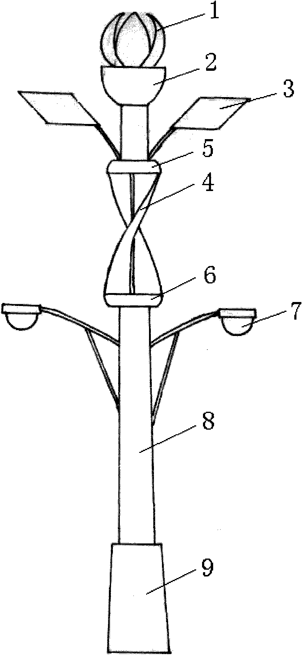
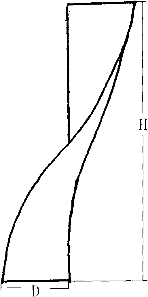
[0029] figure 1 One embodiment of the invention is shown. The upper end of the light pole 8 is equipped with a lotus-shaped paddle assembly 1 made of a half-section propeller blade, which is 55 cm high. Access to the spiral paddle assembly 4, the assembly is equipped with an upper cover seat 5 and a lower cover seat 6 with the upper and lower ends respectively fixing the spiral blades, the height of the assembly is 145cm, and the diameter of the upper and lower cover seats is 60cm , a solar panel 3 is respectively installed on both sides above the assembly, the area of ​​the solar panel is 50×60cm, and an LED lighting lamp 7 is respectively installed on both sides below the assembly, the diameter of the LED lighting lamp is 45cm, and the light pole The lower end of 8 is connected with a light pole base 9, the diameter of the bottom edge of the light...


PUM

PropertyMeasurementUnit
Heightaaaaaaaaaa

Abstract

The invention relates to a light energy and wind energy complementary illumination device on a vertical shaft, relating to the field of an energy device and overcoming the defects of single energy type adoption, unstable electricity supply, high start wind speed, low utilization rate of wind energy, great blade size and inconvenient mounting in a presently used wind energy or light energy illumination device. The invention solves the problems by respectively mounting a plurality of spiral blade assemblies, a plurality of solar panels and lighting lamps at the upper segment of a vertical lamp post which is internally provided with a vertical aerogenerator, each spiral blade assembly is vertically connected into a main shaft of the aerogenerator, the lamp post is also internally provided with an accumulator and a control device, and the solar panels, the aerogenerator, the accumulator, the control device and the lighting lamps are electrically connected. The invention has the advantages of stable electricity supply, high utilization rate of the wind energy, low start wind speed, wide regions of application, small size, convenient mounting, safe use, little noise and attractive appearance.

Description

technical field [0001] The invention relates to the field of energy devices, in particular to an energy device combining wind energy and light energy. Background technique [0002] With the rapid growth of our country's economy, the demand for energy has increased significantly, and the contradiction between energy supply and demand is very prominent, which has seriously affected the development of the economy and the improvement of people's living standards. Commonly used energy sources such as coal, oil, and natural gas have rapidly reduced reserves after long-term overexploitation, and their extensive use has caused serious pollution to the environment, which in turn seriously threatens the survival of human beings. Therefore, it is imperative to find new clean energy sources. [0003] Both wind energy and light energy are inexhaustible clean energy that widely exist in nature, and are ideal alternative energy sources for coal, oil, and natural gas. [0004] Due to the ...

Claims


Application Information

Patent Timeline
IPC IPC(8): F21S9/02F21S9/03F21S9/04F21V23/00H02J7/00F03D9/00
CPCY02E10/72Y02P70/50
Inventor 孙元明顾军李妍
Owner WUXI ANYDA NEW ENERGY TECH
Why Eureka
Try Eureka