
Magnetic assembly and assembling method thereof

A technology of magnetic components and assembly methods, which is applied in the direction of assembling printed circuits with electrical components, electrical components, inductors/transformers/magnets, etc., can solve problems such as difficult processing, increased production costs, and long processing time, and achieve increased induction coils Number, increased sense value, easy assembly effect

Inactive Publication Date: 2011-01-12
DELTA ELECTRONICS INC
View PDF0 Cites 2 Cited by
  • Summary
  • Abstract
  • Description
  • Claims
  • Application Information

AI Technical Summary

Problems solved by technology

[0006] The main purpose of the present invention is to provide a magnetic assembly and its assembly method to solve the problem that the number of winding coils cannot be increased when multiple coils are wound on the annular iron core, so that the inductance cannot be increased, the processing is difficult and the processing time is too long. It is long and needs to be wound manually, which will increase the production cost and other disadvantages

Method used


Image

  • Magnetic assembly and assembling method thereof
  • Magnetic assembly and assembling method thereof
  • Magnetic assembly and assembling method thereof

Examples


Embodiment Construction

[0049] Some typical embodiments embodying the features and advantages of the present invention will be described in detail in the following description. It should be understood that the invention is capable of various changes in different forms without departing from the scope of the invention, and that the description and illustrations therein are illustrative in nature and not limiting.

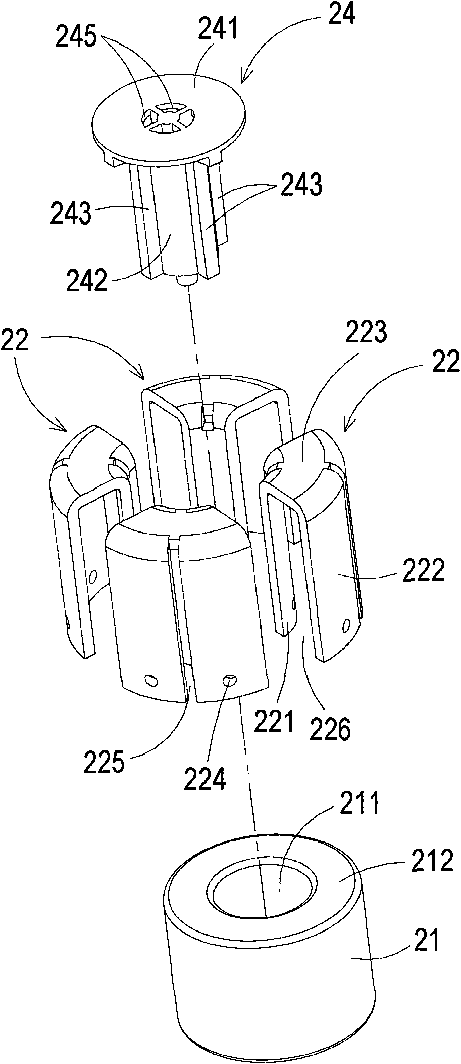
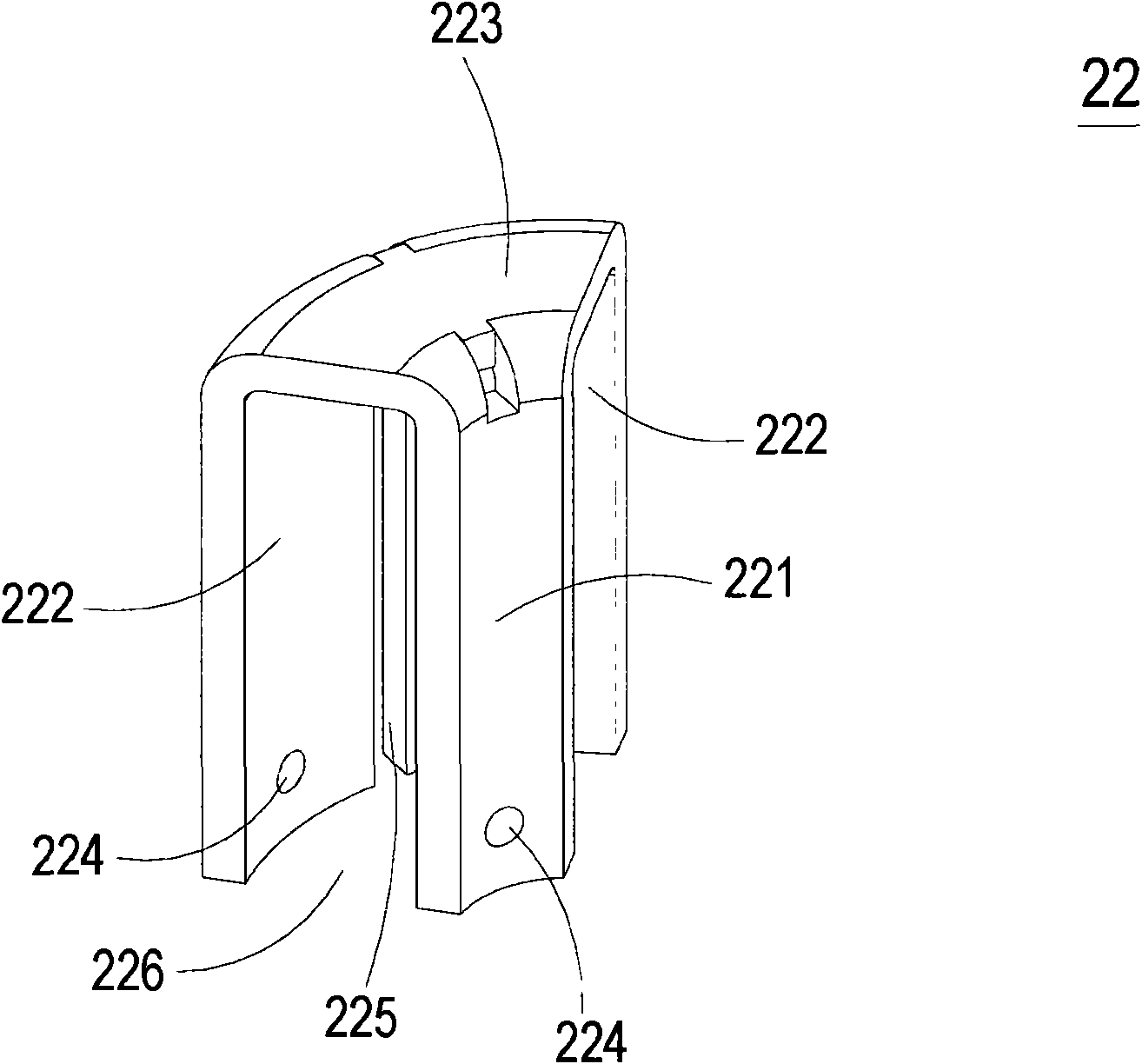
[0050] see figure 2 as well as Figure 6AAs shown, the magnetic component 2 of the present invention includes an iron core 21, a plurality of conductive elements 22 and a circuit board 23; wherein, the circuit board 23 has a plurality of conductive regions 231, and each conductive element 22 has a first end 221 , a second end portion 222 and a connecting portion 223 connecting the first end portion 221 and the second end portion 222 . Wherein a plurality of conductive elements 22 are respectively straddled on the iron core 21, and the first end 221 and the second end 222 of each conducti...


PUM


Abstract

The invention discloses a magnetic assembly and an assembling method thereof. The magnetic assembly at least comprises an iron core, a circuit board and a plurality of conductive elements, wherein the circuit board is provided with a plurality of conductive regions; each conductive element is provided with a first end part, a second end part and a connecting part for connecting the first end part and the second end part; the plurality of conductive elements are respectively arranged across the iron core; and the first end part and the second end part of each conductive element are respectively connected to the two adjacent conductive regions so that the plurality of conductive elements and the plurality of conductive regions form a plurality of numbers of rings on the iron core. The magnetic assembly and the assembling method thereof ensure that the plurality of conductive elements and the plurality of conductive regions form the plurality of numbers of rings on the iron core, and the numbers of sensing rings formed on the iron core can be increased with easy assembly. In addition, the cross sections of the conductive elements arranged on the iron core are same as the public known coils, and sensing values of the magnetic assembly is increased through increasing the thickness of the conductive elements.

Description

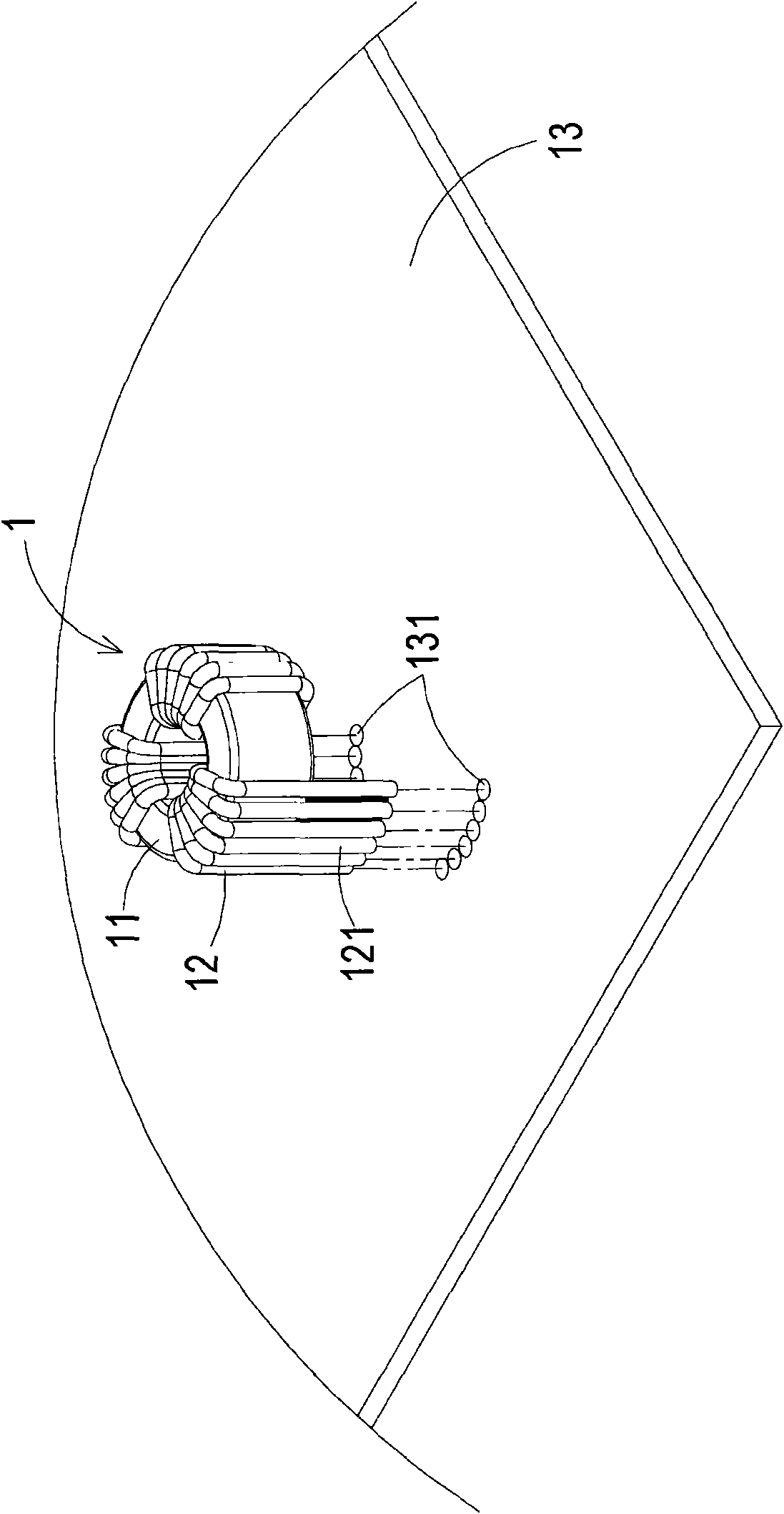
technical field [0001] The invention relates to a magnetic assembly, in particular to a magnetic assembly and an assembly method thereof. Background technique [0002] Many electronic components are usually installed in current electrical products, and various electronic components will generate a large amount of electromagnetic interference (EMI). A large amount of electromagnetic wave interference not only seriously interferes with the work of each electronic component itself, but also seriously interferes with the circuits in electrical products, and even causes damage or failure of electrical products. When the electromagnetic wave interference of electrical products is serious, it will also cause abnormal operation or damage of other electrical products. Therefore, high-frequency filters (Chock) are installed in general electrical products in order to reduce the influence of electromagnetic wave interference on electrical products. [0003] see figure 1 , which is a ...

Claims


Application Information

Patent Timeline
Patent Type & Authority Applications(China)
IPC IPC(8): H01F37/00H05K3/30H01F41/00
Inventor 吴宗学邓经宪廖高材张治良林添昌叶鸣
Owner DELTA ELECTRONICS INC
Learn More