Antenna structure for communication module and manufacturing method thereof

An antenna structure and communication module technology, applied in the direction of loop antennas with ferromagnetic material cores, radiation element structures, etc., can solve the problems of insufficient bonding between integrated circuit chips and near-field communication antennas, and insufficient antenna inductance. Achieve the effects of low cost, improved sense value, and increased reliability

Active Publication Date: 2019-05-14
INPAQ TECH
View PDF4 Cites 0 Cited by
  • Summary
  • Abstract
  • Description
  • Claims
  • Application Information

AI Technical Summary

Problems solved by technology

However, most of the existing near-field communication antennas have a rather large area. Under the current trend of miniaturization of mobile communication products, the size of the near-field communication antenna also needs to be reduced. However, when it is necessary to miniaturize the near-field communication antenna, it will encounter Insufficient antenna inductance. In addition, in the process of miniaturization, the joint between the integrated circuit chip and the pad of the near field communication antenna is not strong enough.

Method used


Image

  • Antenna structure for communication module and manufacturing method thereof
  • Antenna structure for communication module and manufacturing method thereof
  • Antenna structure for communication module and manufacturing method thereof

Examples


Embodiment 1

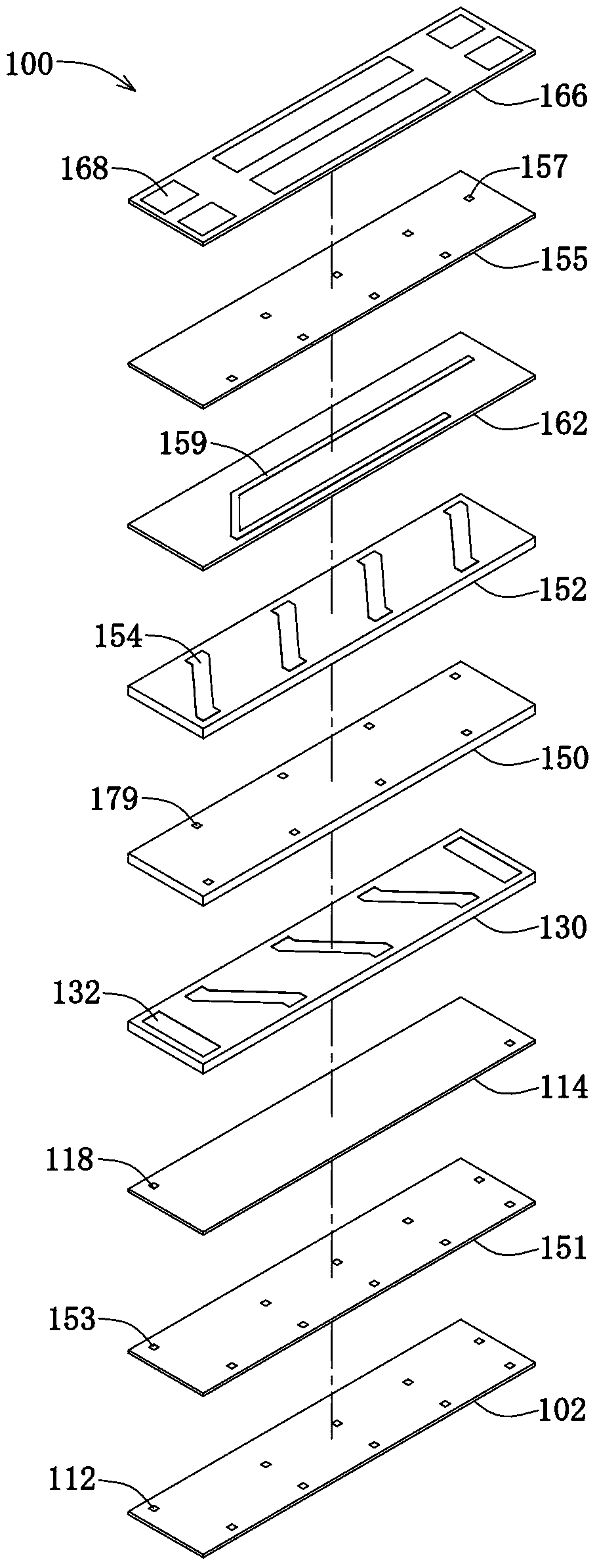
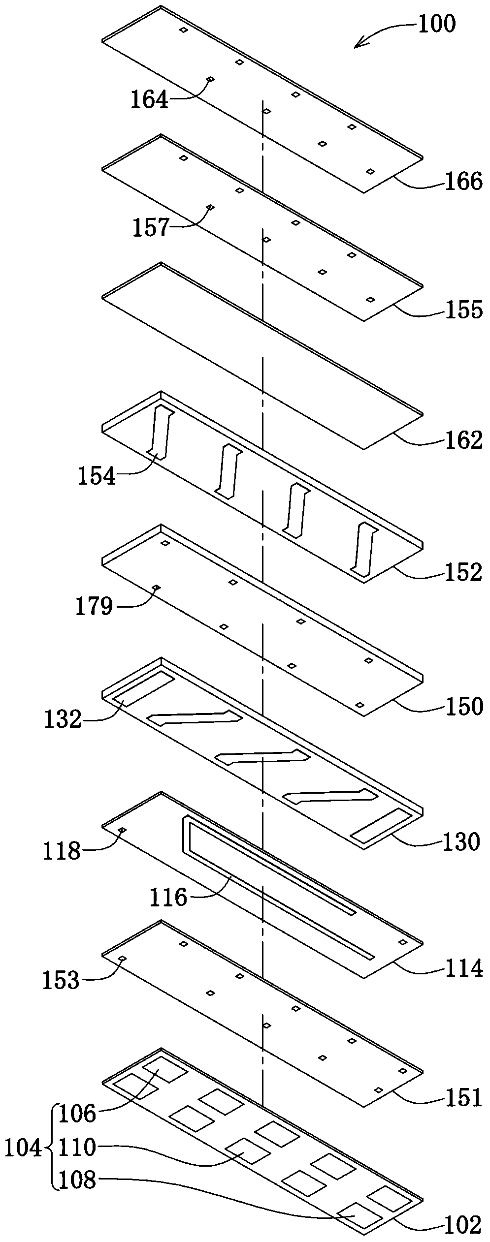
[0052] Figure 1A It is a three-dimensional exploded view of the antenna structure used in the communication module in this embodiment, Figure 1B It is a three-dimensional exploded view from another perspective of the antenna structure used in the communication module in this embodiment. This embodiment provides an antenna structure used in a communication module. More specifically, the antenna structure of this embodiment is used in a wireless communication induction system. Please refer to Figure 1A with Figure 1B In this embodiment, the antenna structure 100 for a communication module includes a first magnetic layer 102, and a plurality of first pad electrodes 104 are arranged on the lower surface of the first magnetic layer 102, wherein the first pad electrodes 104 include a The first feeding pad electrode 106, a second feeding pad electrode 108 and a plurality of dummy (dummy) pad electrodes 110, the first feeding pad electrode 106 and the second feeding pad electrode...

Embodiment 2

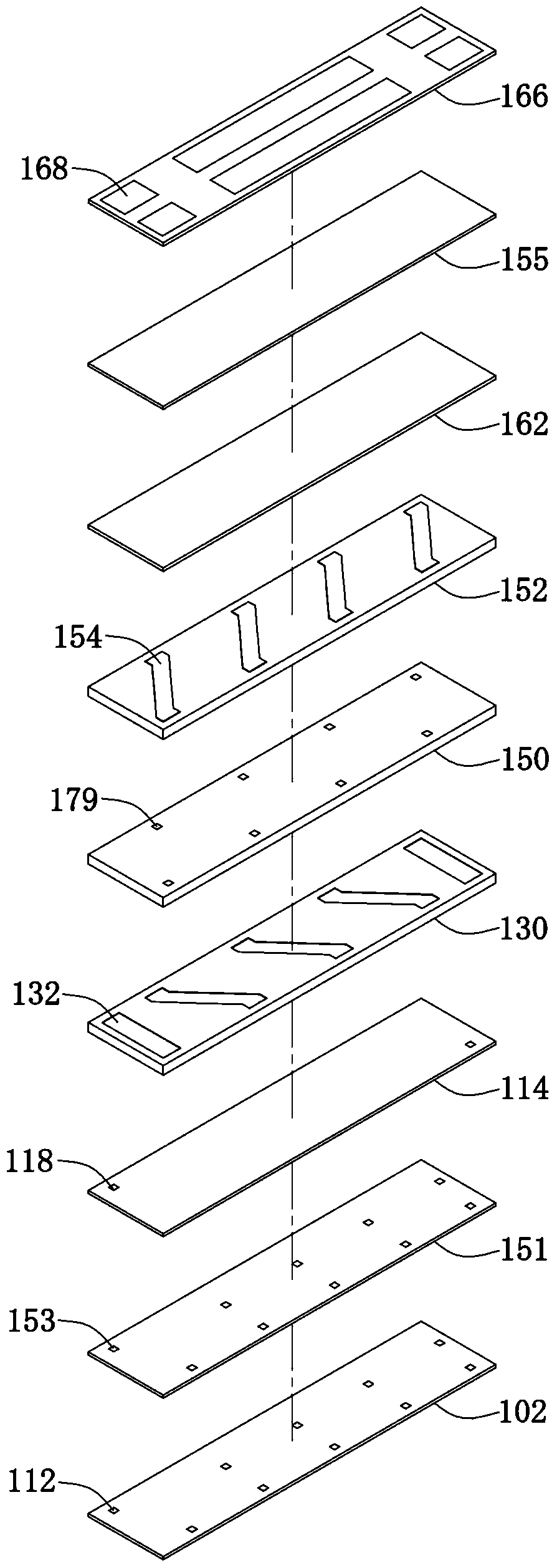
[0064] Figure 2A It is a three-dimensional exploded view of the antenna structure used in the communication module in this embodiment, Figure 2B It is a three-dimensional exploded view from another perspective of the antenna structure used in the communication module in this embodiment. This embodiment provides an antenna structure for a communication module, which, like the antenna structure of the first embodiment, includes a first magnetic layer 102, a first intermediate magnetic layer 151, a second magnetic layer 114, a third magnetic layer Body layer 130, fourth magnetic body layer 150, fifth magnetic body layer 152, sixth magnetic body layer 162, second intermediate magnetic body layer 155 and seventh magnetic body layer 166, and corresponding via conductors and wire-shaped conductor, the difference from the first embodiment is that the sixth magnetic layer 162 and the second intermediate magnetic layer 155 of this embodiment do not form any conductive structure, in o...

Embodiment 3

[0067] Figure 4A It is a three-dimensional exploded view of the antenna structure used in the communication module in this embodiment, Figure 4BIt is a three-dimensional exploded view from another perspective of the antenna structure used in the communication module in this embodiment. This embodiment provides an antenna structure for a communication module, which, like the antenna structure of the first embodiment, includes a first magnetic layer 102, a first intermediate magnetic layer 151, a second magnetic layer 114, a third magnetic layer The body layer 130, the fourth magnetic layer 150, the fifth magnetic layer 152 and the corresponding via conductors and linear conductors therein are different from the first embodiment in that the antenna structure of this embodiment does not include a sixth magnetic body layer, the second intermediate magnetic layer and the seventh magnetic layer.

[0068] Figure 5 It is a flow chart of the method for forming the antenna structu...


PUM


Abstract

The invention relates to an antenna structure for a communication module and a fabrication method thereof. The antenna structure comprises a first magnetic substance layer, a second magnetic substance layer, a third magnetic substance layer, a fourth magnetic substance layer, a fifth magnetic substance layer, a sixth magnetic substance layer and a seventh magnetic substance layer which are sequentially arranged, wherein the third magnetic substance layer, the fourth magnetic substance layer and the fifth magnetic substance layer are internally provided a coil-shaped conductor pattern so as to form a magnetic core structure; the first magnetic substance layer is provided with a plurality of bonding pad electrodes, the seventh magnetic substance layer is provided with a plurality of second bonding pad electrodes, the first bonding pad electrodes comprise a first feed-in bonding pad electrode, a second feed-in bonding pad electrode and a plurality of dummy bonding pad electrodes; the third magnetic substance layer, the fourth magnetic substance layer and the fifth magnetic substance layer all have first magnetic permeability, the first magnetic substance layer, the second magnetic substance layer, the sixth magnetic substance layer and the seventh magnetic substance layer all have second magnetic permeability, and the first magnetic permeability is greater than or equal to the second magnetic permeability. The antenna structure adopts materials with high magnetic permeability in the magnetic substance layers containing the magnetic core structure, so that an inductance value of a small-size antenna can be improved.

Description

technical field [0001] The invention relates to an antenna structure and a manufacturing method thereof, in particular to an antenna structure for a communication module and a manufacturing method thereof. Background technique [0002] Mobile phones or any type of mobile communication devices have become the equipment that modern people carry with them. In the past, the main functions of mobile communication devices were limited to functions known to the public such as making calls, sending text messages, or surfing the Internet wirelessly. However, with the advancement of technology, and due to the portable nature of mobile phones, the industry has begun to conceive of integrating some functions that meet the needs of daily life into mobile phones, such as contactless smart cards. The so-called non-contact smart card is to enable the chip installed in the card to function through the proximity sensing method. At present, there are many occasions where contactless smart ca...

Claims


Application Information

Patent Timeline
Patent Type & Authority Patents(China)
IPC IPC(8): H01Q1/38H01Q7/06
Inventor 郑智宇宇恩佐郑志宏苏志铭
Owner INPAQ TECH
Why Eureka
Try Eureka