Magnetic latching electromagnet with state detection function

A state detection and magnetic holding technology, which is applied in the field of magnetic holding electromagnets, can solve the problems of electromagnet state detection errors, electromagnets are difficult to seal, and cannot satisfy users, so as to improve anti-vibration, ensure reliable connection, and avoid self-deformation Effect

Active Publication Date: 2011-01-12
陕西众力通用电器股份有限公司
View PDF7 Cites 5 Cited by
  • Summary
  • Abstract
  • Description
  • Claims
  • Application Information

AI Technical Summary

Problems solved by technology

This structure is prone to contact vibration under the condition of shock and vibration, which will cause errors in the detection of the state of the electromagnet.
In addition, the lead wires of most electromagnets are mostly soft leads, and the lead parts of the electromagnet are difficult to seal, which cannot meet the requirements of users.

Method used


Image

  • Magnetic latching electromagnet with state detection function
  • Magnetic latching electromagnet with state detection function
  • Magnetic latching electromagnet with state detection function

Examples


Embodiment Construction

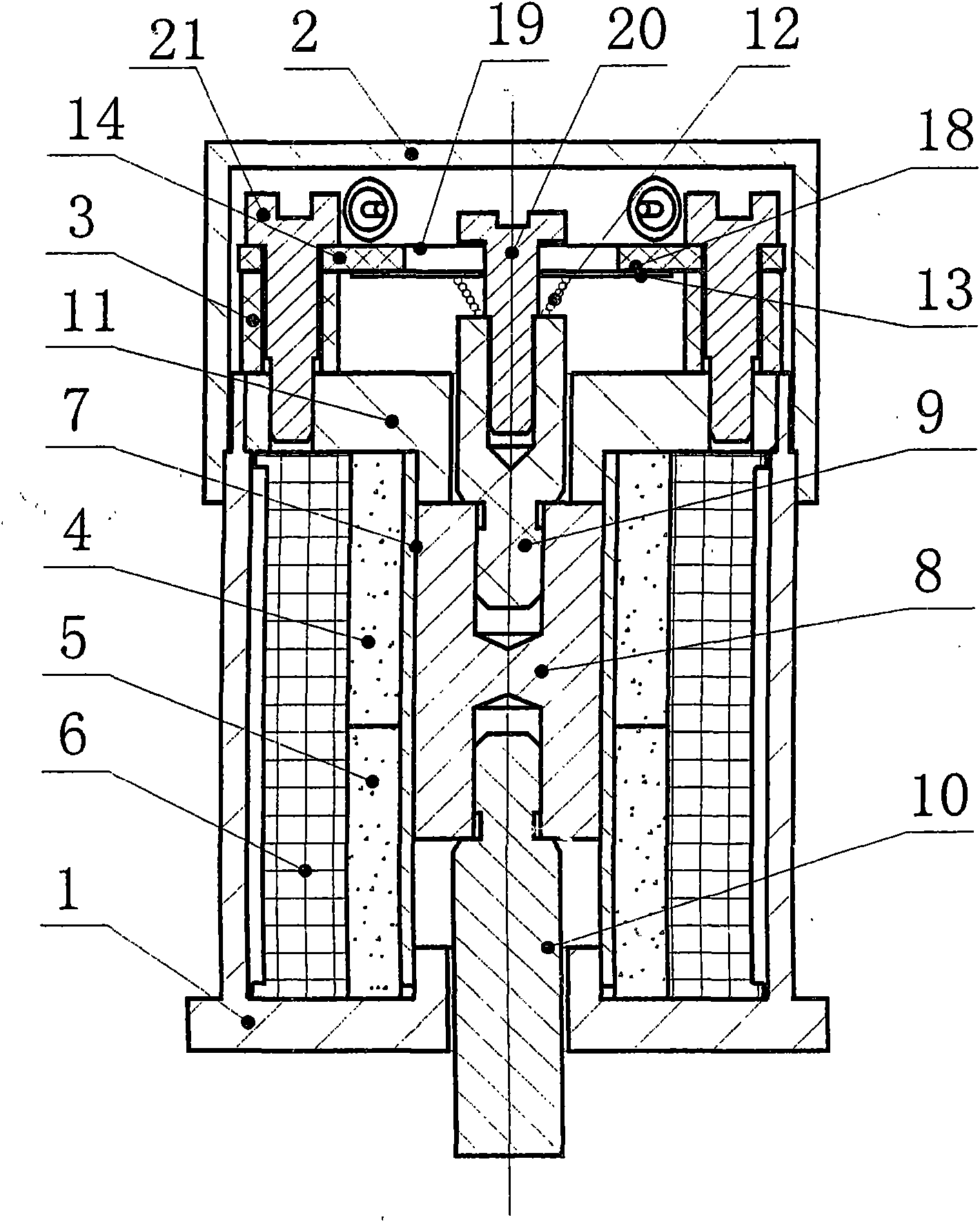
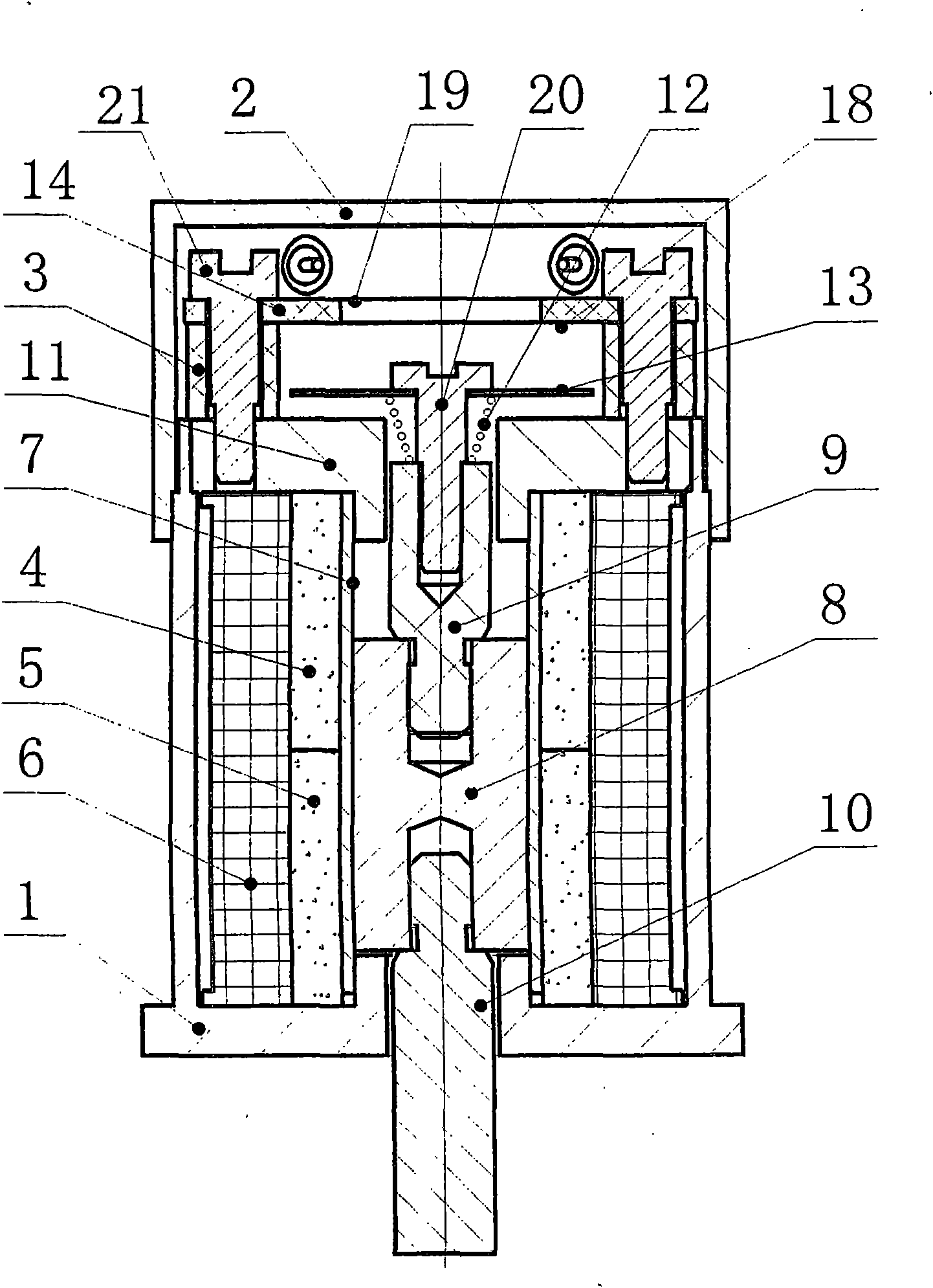
[0017] combined with figure 1 , 2 , 3, 4 describe an embodiment of the present invention.

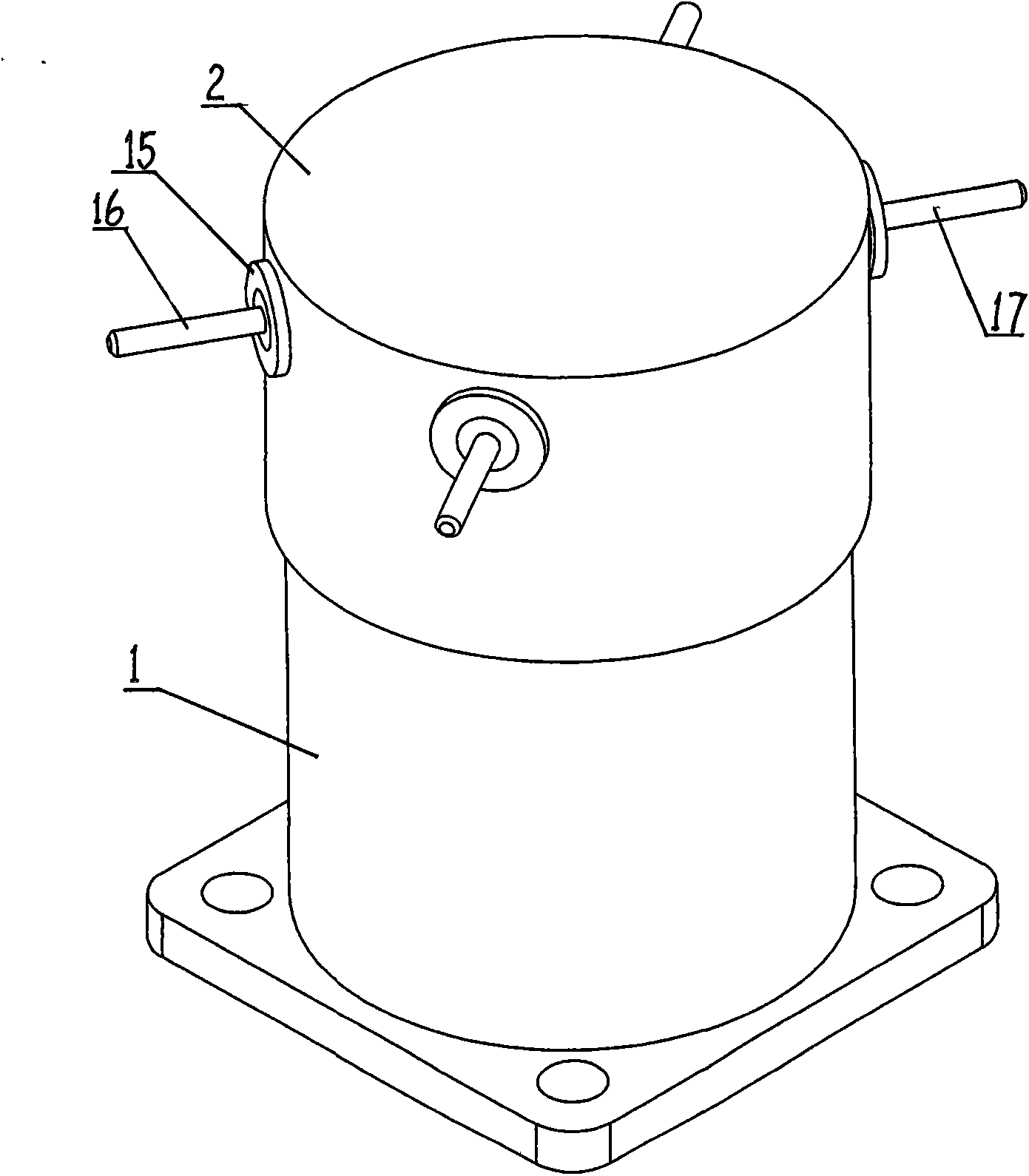
[0018] A magnetic holding electromagnet with state detection has a casing 1 and a casing 2 . Housing 1 is equipped with two ring magnets I 4 and ring magnets II 5 with opposite polarities, ring magnets I 4 and ring magnets II 5 are covered with coil 6, ring magnets I 4 and ring magnets II 5 is inserted with a brass tube 7, and the brass tube 7 is inserted with an armature 8, and the two ends of the armature 8 are respectively connected with an upper push rod 9 and a lower push rod 10, and the upper port of the housing 1 is fixed with a cover plate 11 . The upper push rod 9 passes through the through hole on the cover plate 11 and the top screw 120 is screwed, the tower spring 12 and the moving reed 13 are sleeved on the screw 120, and the tower spring 12 is positioned at the bottom of the moving reed 13. The lower push rod 10 protrudes out of the housing 1 through the through hole a...


PUM


Abstract

The invention discloses a magnetic latching electrode with a state detection function. Two circular steel magnets with opposite polarities are arranged in a shell of the magnetic latching electrode, a coil is externally sleeved on each of the two circular steel magnets, an armature is inserted into each of steel magnets, the two ends of each armature are connected with an upper pushrod and a lower pushrod respectively, a cover plate is fixed at the upper end port of the shell, the upper pushrod passes through a through hole on the cover plate and then the top end of the upper pushrod is sleeved with a tower spring and a moveable spring plate, the tower spring is positioned below the moveable spring plate, and the lower pushrod passes through the through hole at the bottom of the shell to extend out of the shell; and a detection circuit board is fixed on the cover plate and positioned above the moveable spring plate, a housing is clamped on the upper end of the shell to make the cover plate and the detection circuit board positioned in the housing. In the invention, a new magnetic path structure is formed by superposing an electromagnetic path generated by the coil and the magnetic path of the steel magnets, so that the size and weight of the electromagnet are reduced, and the anti-vibration and impact resistance of the magnetic path system are improved; and the deformation of the tower spring supplies a pressure for the moveable spring plate, so that the deformation of the spring plate is avoided and the anti-vibration and impact resistance are further improved. Moreover, an outgoing line of the electromagnet is sealed in and fixed on the housing through a glass insulator, and the sealing requirement of the electromagnet is met.

Description

technical field [0001] The invention belongs to the technical field of magnetic holding electromagnet manufacturing, and in particular relates to a magnetic holding electromagnet with state detection. Background technique [0002] The volume and quality of the existing magnetic holding electromagnet are large. And the state detection is to push the moving reed inside the electromagnet when the armature moves after the coil is excited, so that the moving reed is deformed, and the moving reed and the static reed are connected or disconnected, so as to judge the state of the electromagnet is in the desired state. Under the conditions of impact and vibration, this structure is prone to contact vibration, which will cause errors in the state detection of the electromagnet. In addition, the lead wires of most electromagnets are mostly soft leads at present, and the lead wire parts of the electromagnet are difficult to seal, which cannot meet the requirements of users. Contents...

Claims


Application Information

Patent Timeline
Patent Type & Authority Applications(China)
IPC IPC(8): H01H51/01
Inventor 雷建伟
Owner 陕西众力通用电器股份有限公司
Why Eureka
Try Eureka