Passive mode-locking fiber laser delay feedback chaotization system based on graphene

A fiber laser, passive mode-locking technology, applied in lasers, optical transmission systems, laser components, etc., can solve the problems of saturable absorption loss and low damage threshold, and achieve high peak power, easy synchronization, and high damage threshold. Effect

Inactive Publication Date: 2011-01-12
JILIN UNIV
View PDF3 Cites 24 Cited by
  • Summary
  • Abstract
  • Description
  • Claims
  • Application Information

AI Technical Summary

Benefits of technology

In this patented technology, there are several technical features related to generating short optically pulsed signals through a special type called a quantum dots crystal. These techniques allow for precise timing and generation of longer opticacons without requiring extra components like electromodulated devices at any cost. Additionally, they use advanced materials such as carbon nanotubbles instead of traditional semiconductor elements which make up these systems more reliable but less efficient than other alternatives. Overall, their advantages include improved efficiency, reliability, safety, and ease of implementation across different industries while being suitable for various applications where security needs to be provided over long distances.

Problems solved by technology

Technological Problem: Current Optically Stabilized LC Laser System uses quantum dots instead of traditional stabilizing methods like phase locked loop techniques that require complicated manufacturing process steps. Additionally, current proposals involve using special types of fibers called CWs, including superficial ones made from plasma telecommunicated sapphire crystallites, which limits their applicability within certain fields where fast speeds and reliance were necessary.

Method used


Image

  • Passive mode-locking fiber laser delay feedback chaotization system based on graphene
  • Passive mode-locking fiber laser delay feedback chaotization system based on graphene
  • Passive mode-locking fiber laser delay feedback chaotization system based on graphene

Examples


Embodiment 1

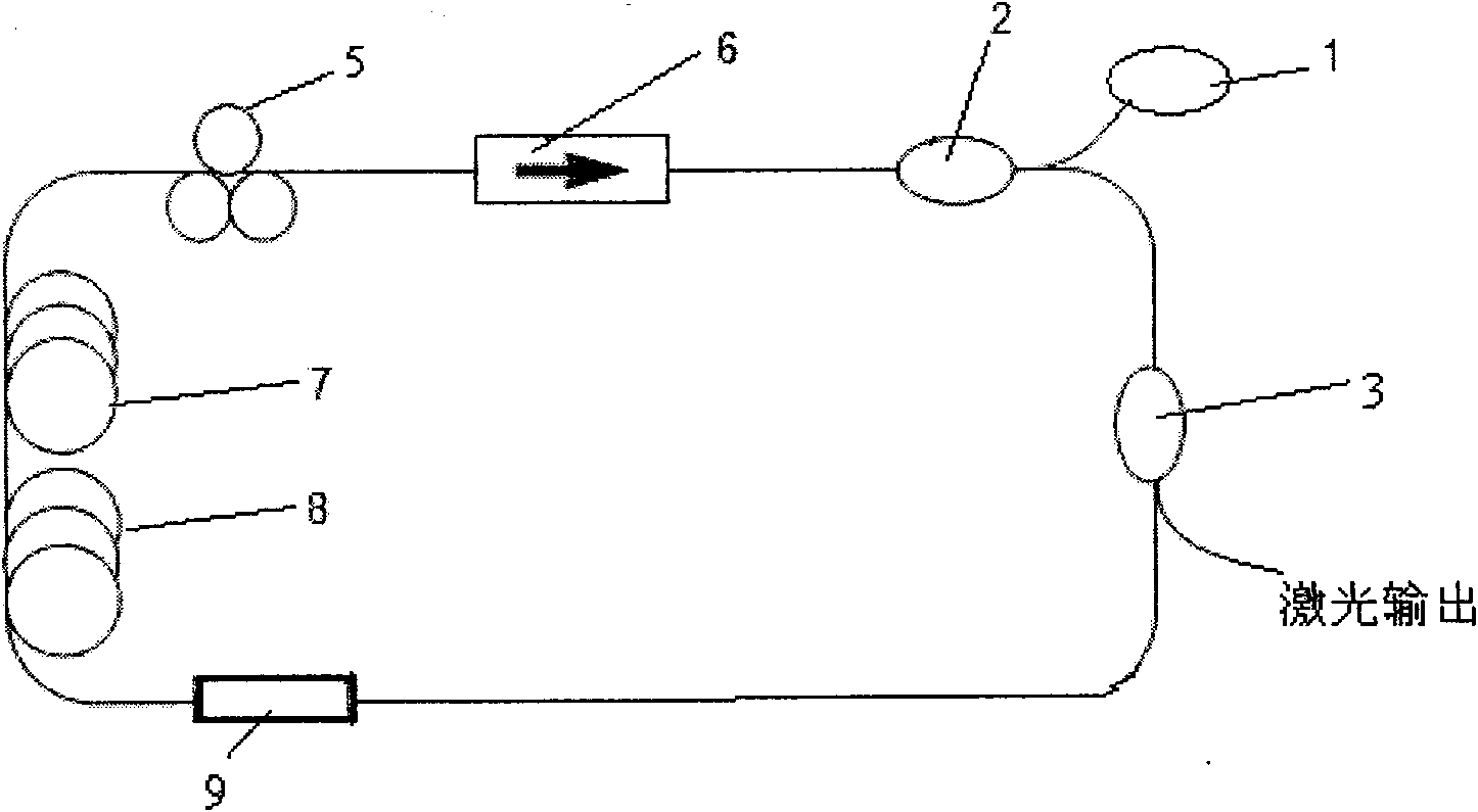
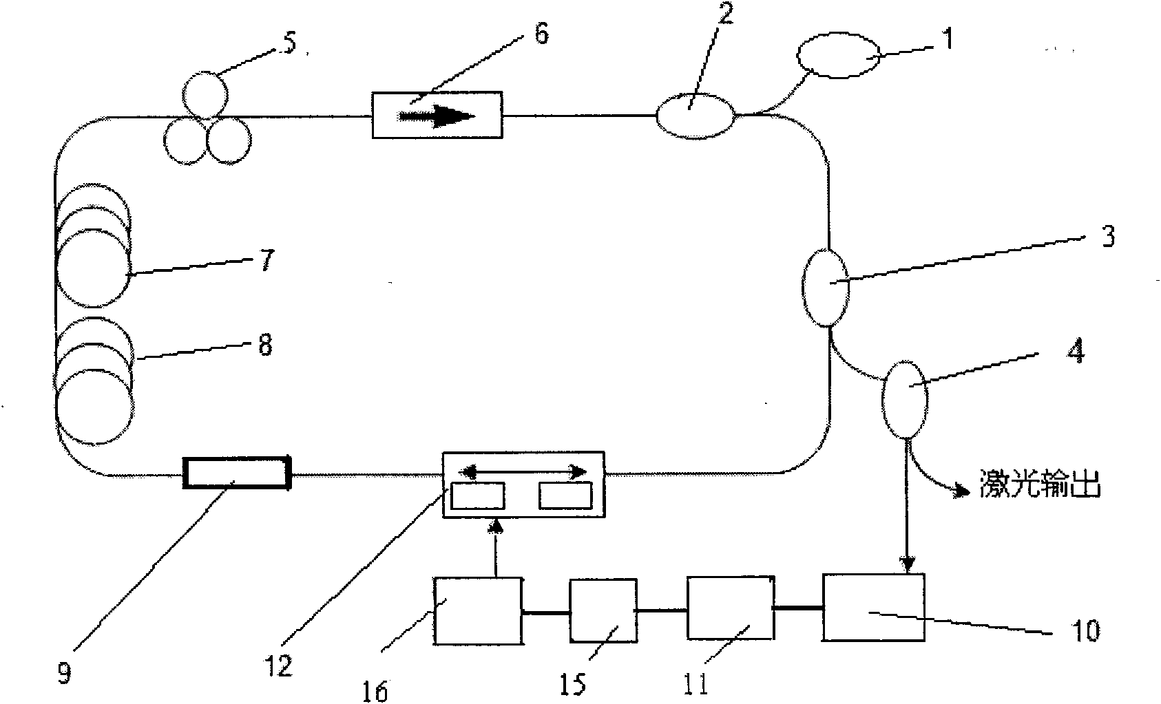
[0021] The present invention is based on the graphene-based passive mode-locked fiber laser delay feedback chaotic system structure as follows figure 2 shown. figure 2 Among them, 1 is the pump laser, which can use the 1480nm Raman fiber laser produced by the American IPG PHOTONICS CORPORATION company, with an output power of 1W; 2 is the wavelength division multiplexing fiber coupler, which can be produced by Shanghai Hanyu Optical Fiber Communication Technology Co., Ltd. Fused tapered 1480 / 1550nm pump light wavelength division multiplexing coupler; 3 is the first fiber coupler, which can use the 1×2 standard single-mode fiber coupler produced by Shanghai Hanyu Optical Fiber Communication Technology Co., Ltd., with a splitting ratio of 1 : 9; 4 is the second fiber coupler, which can use the 1×2 standard single-mode fiber coupler produced by Shanghai Hanyu Optical Fiber Communication Technology Co., Ltd., with a splitting ratio of 3:7; 5 is the polarization controller, which...

Embodiment 2

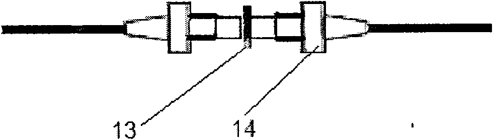
[0024] image 3 The structure of the graphene mode-locking device 9 of the present invention is given. image 3 Among them, 13 is a graphene sheet; 14 is a FC / PC optical fiber connector, which can use the standard FC / PC optical fiber connector produced by Shanghai Hanyu Optical Fiber Communication Technology Co., Ltd.

[0025] Graphene mode-locking device 9 comprises graphene sheet 13 and FC / PC optical fiber connector 14 on both sides of graphene sheet 13, and graphene sheet 13 and FC / PC optical fiber connector 14 constitute graphene mode-locking device 9 for producing lock mode ultrashort light pulses.


PUM

PropertyMeasurementUnit
Lengthaaaaaaaaaa
Lengthaaaaaaaaaa

Abstract

The invention belongs to the technical field of optical communication devices and relates to a passive mode-locking fiber laser delay feedback chaotization system based on graphene, comprising a pumping laser (1), a wavelength division multiplexing fiber coupler (2), a first fiber coupler (3), a mode-locking device (9), an erbium-doped fiber (7), a polarization controller (5), an isolator (6), a second fiber coupler (4), a photodetector (10), an A/D conversion circuit (11), a single chip microcomputer (15), an RS 232 interface (16) and an optical delay line (12), wherein the optical delay line (12) receives control signals and carries out delay feedback to enable the whole system to be in a chaotization state, and the mode-locking device (9) is a graphene mode-locking device. The invention can generate a femto-second order optical pulse without an external modulation source, has the advantages of easy synchronization, high output pulse peak power, easy installation and operation and simple structure, and the like and can realize all-fiber integration and create the foundation of realizing chaotization synchronization and secrete communication.

Description


Claims


Application Information

Patent Timeline
Owner JILIN UNIV
Why Eureka
Try Eureka