Method, system and device for establishing label switch path

A label-switched path and establishment method technology, applied in the field of label-switched path establishment, can solve the problems of not providing an LSP boundary determination scheme, and being unable to automatically trigger the creation of lower-layer LSPs.

Active Publication Date: 2011-01-12
ZTE CORP
View PDF6 Cites 20 Cited by
  • Summary
  • Abstract
  • Description
  • Claims
  • Application Information

AI Technical Summary

Problems solved by technology

[0012] However, in the prior art, there is no solution for judging the boundary of the LSP, so that it is impossible to automatically trigger the creation of the lower-layer LSP

Method used


Image

  • Method, system and device for establishing label switch path
  • Method, system and device for establishing label switch path
  • Method, system and device for establishing label switch path

Examples


Embodiment 1

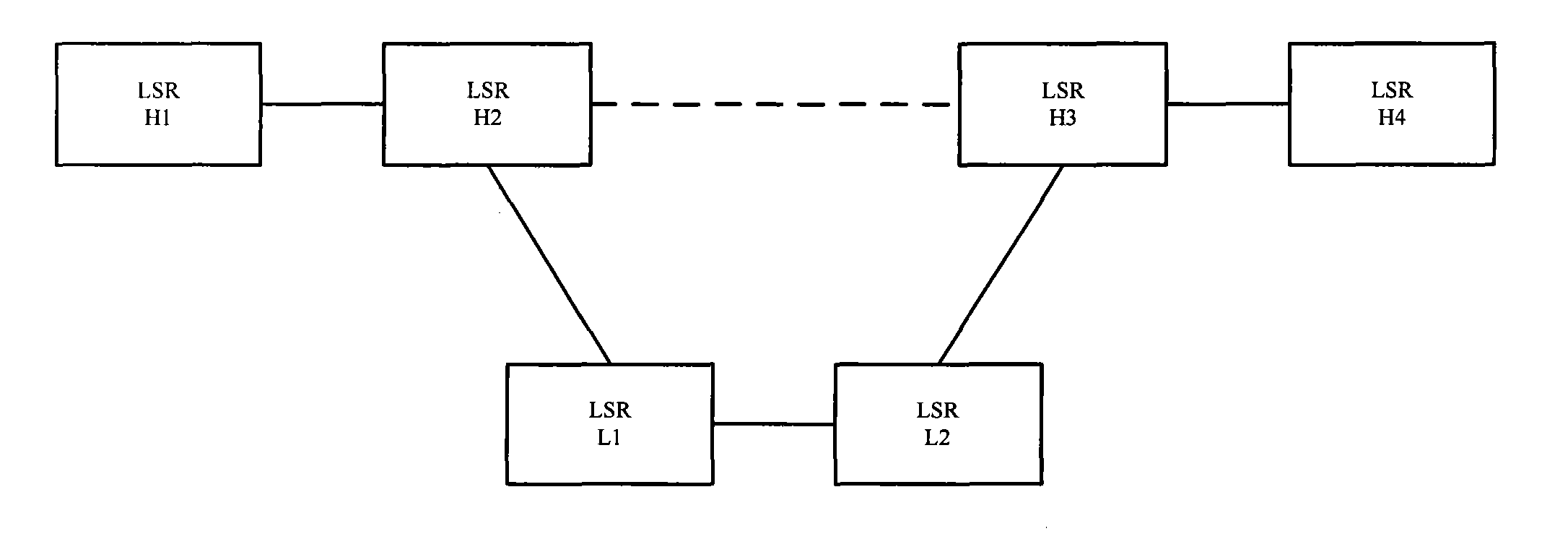
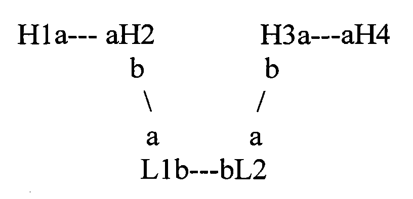
[0090] see image 3 , the network shown in this figure includes two layers, H1, H2, H3, and H4 are LSR nodes of the upper layer network, and H2, L1, L2, and H3 are LSR nodes of the lower layer network. Among them, H2 and H3 are domain boundary nodes, and are also boundary nodes of the lower layer LSP. a and b represent the interfaces on the nodes. For example, in the figure, node H1 is connected to interface a (upstream interface) of H2 through interface a (downstream interface), and H2 is connected to interface a (upstream interface) of L1 through interface b (downstream interface). .

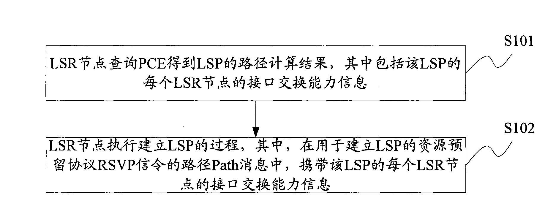
[0091] H1 requests to create an LSP from H1 to H4, H1 first sends a routing query request to PCE, PCE calculates the path from H1 to H4, and then returns the result to H1, and informs each ERO of the LSP and the interface of each ERO in the returned result Switchability and crossover granularity.

[0092] After H1 receives the PCE Rep message, it also carries the ERO object in the PC...

Embodiment 2

[0096] Embodiment 2 (the cross granularity information of the ERO object does not need to be carried in the PATH message):

[0097] Figure 4 The network shown consists of three layers, and the establishment of nested LSPs, where H1, H2, H3, and H4 are the LSR nodes of the upper layer network, M1, M2 are the LSR nodes of the lower layer network, and L1, L2 are the lower layer network LSR nodes.

[0098] H1 requests to create an LSP from H1 to H4, H1 first sends a routing query request to PCE, PCE calculates the path from H1 to H4, and then returns the result to H1, and informs each ERO of the LSP and the interface of each ERO in the returned result exchange capacity.

[0099] After H1 receives the PCE Rep message, it carries the ERO object and its sub-object Switching Type in the PCE Rep message in the Path message.

[0100] The head node H1 analyzes the ERO object and its Switching Type sub-object carried in the Path message, and determines that the switching ca...

Embodiment 3

[0104] Figure 5 Shown is a scenario where LSPs traverse multiple lower-layer networks, where H1, H2, H3, and H4 are upper-layer network nodes, and L1, L2, L3, and L4 are lower-layer network LSR nodes, where L1, L2, L3, and L4 can be the same An LSR node of a network of one switching type, or an LSR node of a network of a different switching type.

[0105] H1 requests to create an LSP from H1 to H4, H1 first sends a routing query request to PCE, PCE calculates the path from H1 to H4, and then returns the result to H1, and informs each ERO of the LSP and the interface of each ERO in the returned result Switchability and crossover granularity.

[0106] After H1 receives the PCE Rep message, it carries the ERO object and its sub-objects Switching Type and Traffic Parameters in the PCE Rep message in the Path message.

[0107] The first node H1 analyzes the ERO object carried in the Path message and its Switching Type and TrafficParameters sub-objects, and determines th...


PUM


Abstract

The invention discloses a method, a system and a device for establishing a label switch path (LSP) for realizing the judgment of an LSP boundary so as to automatically trigger the creation of a lower-level LSP. The method for establishing a label switch path (LSP) comprises the following steps: label switch router (LSR) nodes acquire LSP path computation results obtained by inquiring a path computing element (PCE), wherein the path computation result includes interface switching capability information of each LSR node of the LSP; and the LSR nodes execute a process of establishing the LSP, wherein the interface switching capability information of each LSR node of the LSP is carried by a Path message of a path for establishing the resource reservation protocol (RSVP) signaling of the LSP.

Description

technical field [0001] The present invention relates to the field of communication technology, in particular to a method, system and device for establishing a label switching path. Background technique [0002] Multi-Protocol Label Switching (MPLS, Multi-Protocol Label Switching) and Generalized Multi-Protocol Label Switching (GMPLS, Generalized Multi-protocol Label Switching) networks may include both domains and layers. Domain is a collection of network elements divided for managing common addresses or for path calculation. Wherein, both the Autonomous System (AS) and the Interior Gateway Protocol Area (IGP Area, Interior Gateway Protocol Area) are Domains. AS is a collection of routers that exchange routing information with each other through a common routing protocol. IGPArea is an area that runs an IGP algorithm independently. The topology information inside an IGP Area is invisible to the outside of the IGPA Area, and the internal routers of a given IGPA Area do not...

Claims


Application Information

Patent Timeline
Patent Type & Authority Applications(China)
IPC IPC(8): H04L12/56H04L29/06H04L45/50
Inventor 汪学蓉
Owner ZTE CORP
Why Eureka
Try Eureka