
Terminal and audio signal output method

A technology for audio output and signal output, applied in the field of signal processing, can solve problems such as increasing product cost and affecting received sound quality, and achieve the effect of saving design and manufacturing costs

Active Publication Date: 2011-01-12
HUAWEI DEVICE CO LTD
View PDF3 Cites 12 Cited by
  • Summary
  • Abstract
  • Description
  • Claims
  • Application Information

AI Technical Summary

Problems solved by technology

The receiver signal channel and the speaker signal channel are isolated by a large capacitor to avoid the mutual influence of the DC level of the receiver signal and the speaker signal, but the setting of the capacitor will increase the cost of the product, and the capacitor will affect the receiving sound quality
[0003] The second specific implementation method of two-in-one speaker and receiver is to isolate the signal channel of the receiver and the signal channel of the speaker through a switch, and switch between the signal of the receiver and the signal of the speaker by controlling the opening and closing of the switch, but this kind of switch setting will also increase the cost of the product

Method used


Image

  • Terminal and audio signal output method
  • Terminal and audio signal output method
  • Terminal and audio signal output method

Examples


Embodiment 1

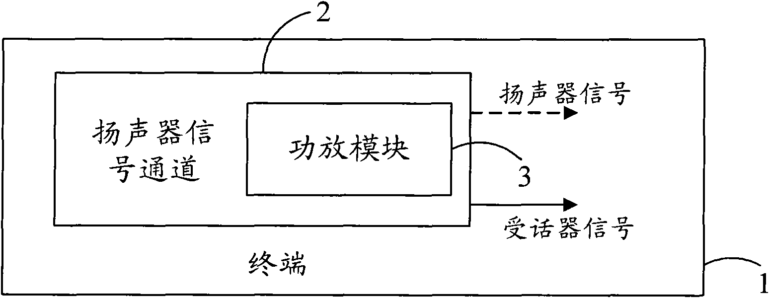
[0020] see figure 1 , a terminal 1, comprising: a speaker signal channel 2, configured to form a receiver signal and output the receiver signal; wherein, the speaker signal channel 2 includes a power amplifier module 3.

[0021] The loudspeaker signal and the receiver signal are audio signals with differences in signal amplitude and DC component formed by processing the baseband signal based on different application requirements. The receiver signal has a lower signal amplitude than the speaker signal. The terminal switches the output of the receiver signal and the speaker signal according to application requirements.

[0022] The loudspeaker signal channel in the prior art refers to the path formed by the devices and lines through which the loudspeaker signal passes during the process of converting the baseband signal into a loudspeaker signal in the terminal and outputting the loudspeaker signal to the audio output module, including a loudspeaker signal processing module (fo...

Embodiment 2

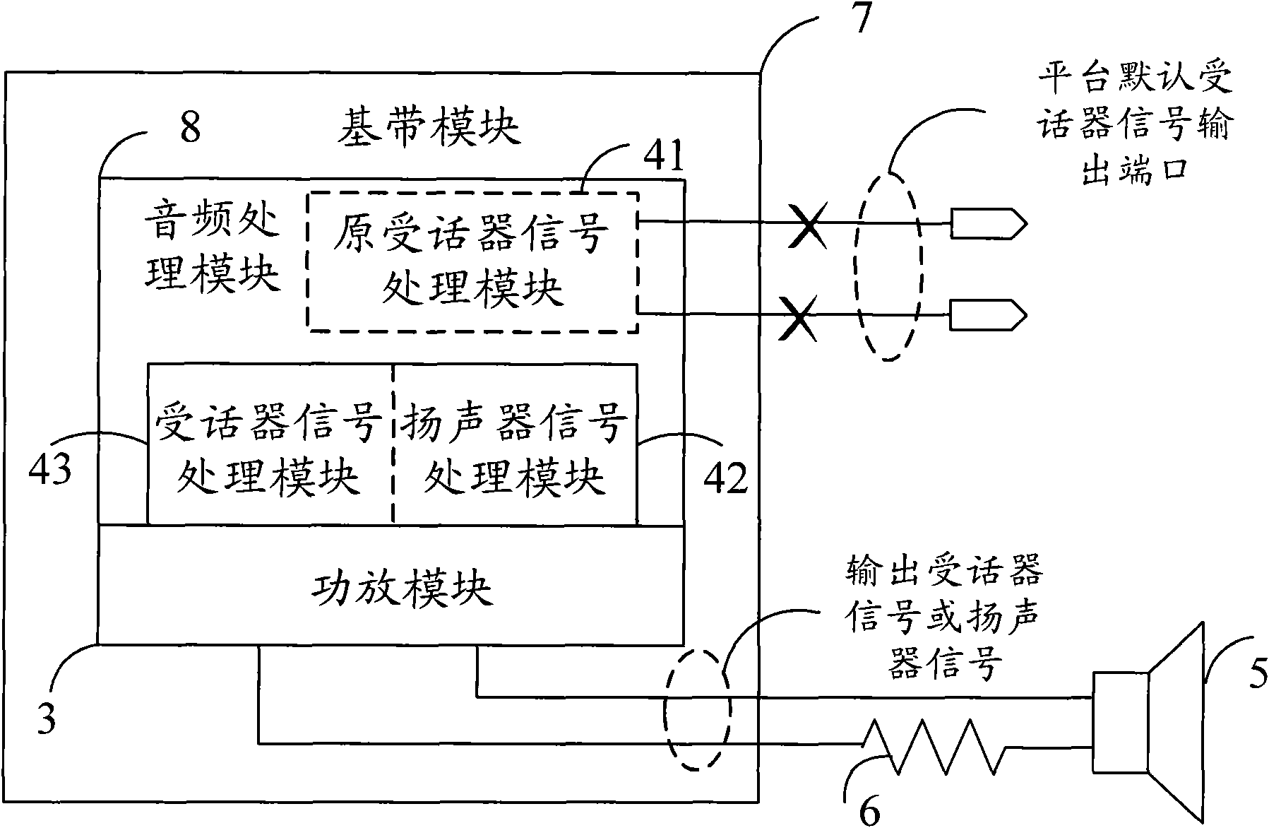
[0038] see Figure 4 , the embodiment of the present invention also provides an audio signal output method, including:

[0039] Step 1, forming a receiver signal.

[0040] Step 2. The speaker signal channel outputs the receiver signal; wherein, the speaker signal channel includes a power amplifier module.

[0041]The loudspeaker signal and the receiver signal are audio signals with differences in signal amplitude and DC component formed by processing the baseband signal based on different application requirements. The receiver signal has a lower signal amplitude than the speaker signal. The loudspeaker signal channel refers to the channel that converts the baseband signal into a loudspeaker signal in the terminal and outputs the loudspeaker signal to the audio output module. processing to form the speaker signal), a power amplifier module and a feedback circuit, etc. The terminal that outputs the audio signal switches the output of the receiver signal and the speaker signal...


PUM


Abstract

The embodiment of the invention discloses a terminal and an audio signal output method, which relate to the technical field of signal processing and are designed for saving the cost of a two-in-one scheme of a loudspeaker and a receiver. The terminal of the embodiment comprises a loudspeaker signal channel which is used for forming receiver signals and outputting the receiver signals and comprises a power amplification module. The embodiment of the invention also provides the audio signal output method which comprises the following steps of: forming the receiver signals; and outputting the receiver signals by the loudspeaker signal channel, wherein the loudspeaker signal channel comprises the power amplification module. The embodiment of the invention is used for outputting audio signals.

Description

technical field [0001] The present invention relates to the technical field of signal processing, in particular to a terminal and an audio signal output method. Background technique [0002] At present, in the application of the terminal platform, there is a solution of combining a loudspeaker and a receiver into one. One of the specific implementation methods for combining the speaker and the receiver into one is to connect a large capacitor in series between the signal channel of the receiver and the audio output module (for example, a composite speaker and receiver). The receiver signal channel is the device and circuit required in the process of converting the baseband signal into the receiver signal and outputting the receiver signal to the audio output module, such as a signal processing module converting the baseband signal into the receiver signal. The receiver signal channel and the speaker signal channel are isolated by a large capacitor to avoid the mutual influe...

Claims


Application Information

Patent Timeline
IPC IPC(8): H04M1/00H04M1/60
CPCH04M1/6041H04R2201/028
Inventor 黄延龙
Owner HUAWEI DEVICE CO LTD
Learn More