Unlock instant, AI-driven research and patent intelligence for your innovation.

Boot for constant velocity universal joint

A technology of constant velocity universal joints and guards, which is applied in the direction of elastic couplings, bellows, mechanical equipment, etc., and can solve the problems of reduced durability

Inactive Publication Date: 2011-01-12
NTN CORP
View PDF6 Cites 5 Cited by
  • Summary
  • Abstract
  • Description
  • Claims
  • Application Information

AI Technical Summary

Problems solved by technology

The uneven thickness and shape of such a shoulder, the impact of foreign objects (such as small stones, etc.) from the outside, and the change of the cover caused by the operation of the constant velocity universal joint will cause stress concentration, and there will be a decrease in durability. possibility of

Method used


Image

  • Boot for constant velocity universal joint
  • Boot for constant velocity universal joint
  • Boot for constant velocity universal joint

Examples


Embodiment Construction

[0034] Hereinafter, the best mode for carrying out the present invention will be described.

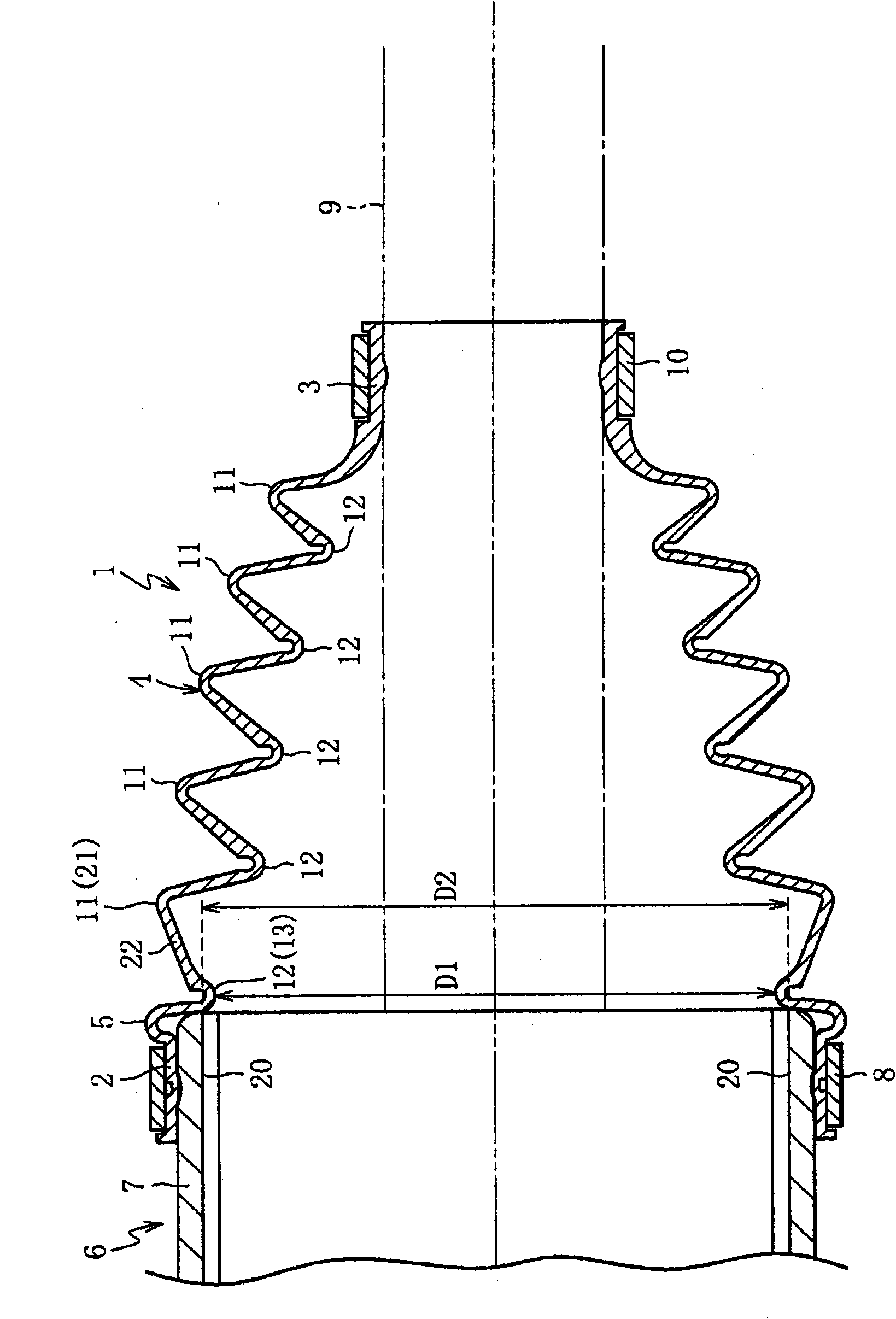
[0035] figure 1 This is a state in which the constant velocity universal joint boot in the embodiment of the present invention is attached to the constant velocity universal joint with an operating angle of 0° and the shaft. The constant velocity universal joint boot is usually installed under compression or tension, but for convenience, in this state, the constant velocity universal joint boot is practically not subjected to axial force due to the constant velocity universal joint and the shaft. The shroud 1 has a large-diameter portion 2, a small-diameter portion 3, a meander portion 4, and a shoulder portion 5 as main constituent elements. The constant velocity universal joint 6 in this embodiment is a double offset type constant velocity universal joint which is a sliding type constant velocity universal joint. The constant velocity universal joint 6 mainly includes an outer jo...


PUM


Abstract

A boot for a constant velocity universal joint can be appropriately fitted on an outer joint member of the joint and has enhanced durability. A shoulder (5) and a root (13) of the boot (1) have a circular arc section (14) and a rectilinear section (15). The circular arc section (14) is located adjacent a large-diameter section (2) and has an axial cross-sectional shape projecting radially outward. The rectilinear section (15) is located adjacent the circular arc section (14) and has an axial cross-sectional shape which is rectilinear. The inner peripheral surface (16) of the rectilinear section (15) is made to contact with an opening end (17) of the outer joint member (7) of the constant velocity universal joint (6). The thickness of the boot (1) from the circular arc section (14) to the rectilinear section (15) is uniform.

Description

technical field [0001] The present invention relates to a shroud installed, for example, on a constant velocity universal joint in a power transmission mechanism of an automobile. Background technique [0002] As is well known, a constant velocity universal joint incorporated in a power transmission mechanism of an automobile, for example, is equipped with a guard to prevent foreign matter such as dust from entering the joint and to prevent grease sealed inside the joint from leaking. [0003] Such shields, such as Figure 4 shown. The shroud 31 has a large-diameter portion 32 , a small-diameter portion 33 , a meander portion 34 , and a shoulder portion 35 as main constituent elements. On the other hand, the constant velocity universal joint 36 has an outer joint member 37, an inner joint member (not shown), and a torque transmission member (not shown) interposed between the outer joint member 37 and the inner joint member to transmit torque. shown) as the main components....

Claims


Application Information

Patent Timeline
IPC IPC(8): F16D3/84
CPCF16D3/845F16J3/042
Inventor 高部真一
Owner NTN CORP