Steel dental plate crusher and manufacture method thereof

A technology of pulverizer and steel tooth plate, which is applied in the direction of grain processing, etc., can solve the problems of no cutting function, breakage, and low production efficiency, and achieve the effects of reducing raw material and power consumption, prolonging service life, and improving production efficiency

Inactive Publication Date: 2011-01-19
赵彬怀
View PDF6 Cites 9 Cited by
  • Summary
  • Abstract
  • Description
  • Claims
  • Application Information

AI Technical Summary

Problems solved by technology

[0003] 1) The tooth plate is usually made of cast iron, and the top of the tooth bar is a blunt arc-shaped structure, which can only impact and crush the material, but has no cutting function, especially when crushing fibrous materials such as straw and medicinal materials, the efficiency is very low; Secondly, although the tooth plate and tooth bar made of cast iron have good compressive strength and wear resistance, their toughness is very poor, especially in the crushing of ore-like hard materials, they are easy to break and break off, which will cause equipment damage accidents.
[0004] 2) In order to ensure sufficient st

Method used


Image

  • Steel dental plate crusher and manufacture method thereof
  • Steel dental plate crusher and manufacture method thereof
  • Steel dental plate crusher and manufacture method thereof

Examples


Embodiment 1

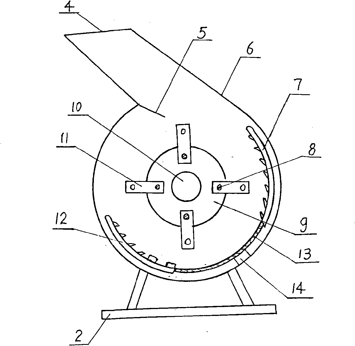
[0030] The manufacture method of this pulverizer is to carry out as follows:

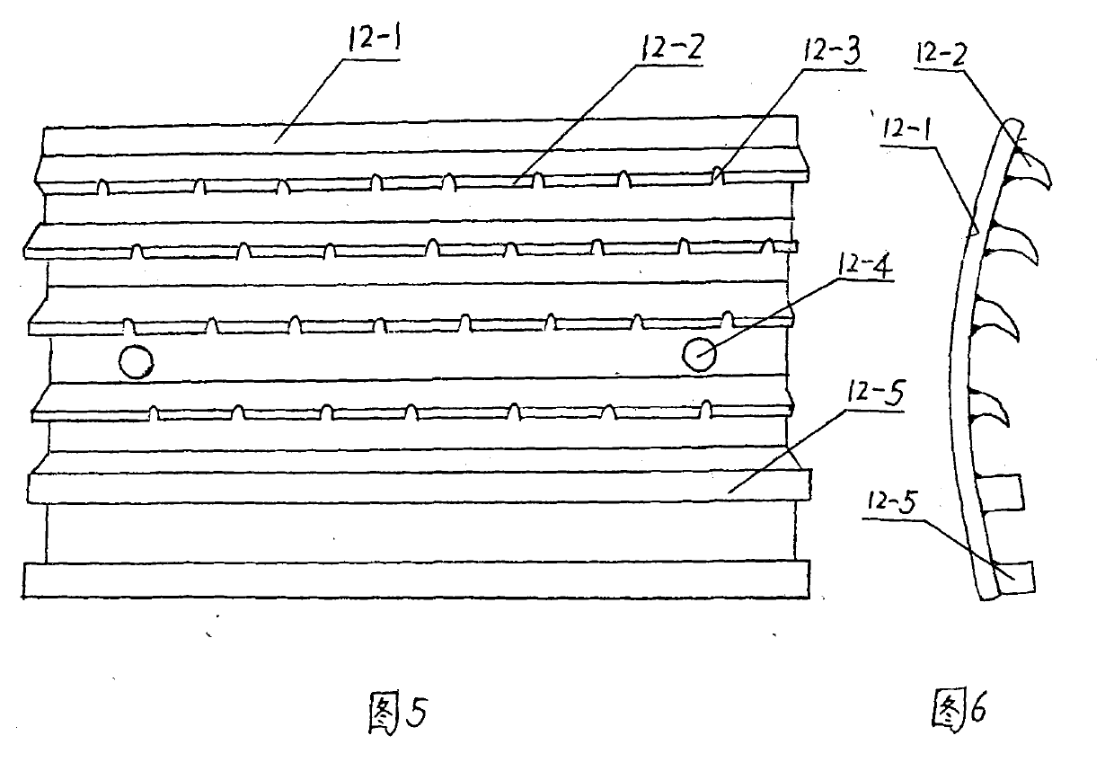
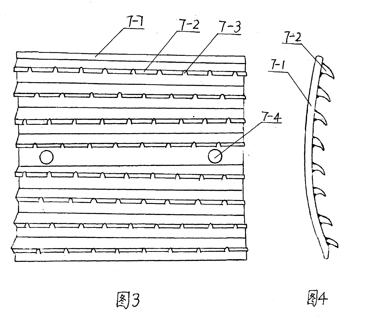
[0031] 1) The main tooth plate blank and the auxiliary tooth plate blank are produced by welding and forming: according to the set process requirements, the low carbon steel plate is taken to intercept the arc-shaped substrate blank, the fixed blade blank and the grinding bar blank respectively, and the arc The arc-shaped base plate blanks are respectively rolled and formed, and are welded together with the fixed blade blanks and the grinding rod blanks. Among them, the thickness of the plate used for the fixed blade blanks is 2mm, and the main tooth plate blanks and auxiliary tooth plate blanks are made. And complete the processing of the mounting holes;

[0032] 2) Manufacturing of pin shaft blanks and movable blade blanks: According to the set process, the pin shaft blanks and movable blade blanks are blanked and processed for later use, and the thickness of the plate used for the movable blades ...

Embodiment 2

[0038] The manufacturing method of the pulverizer of this embodiment is basically the same as that of Example 1, the only difference being: in step 1), the thickness of the plate used for the fixed blade blank is 3 mm; in step 2), the thickness of the plate used for the movable blade is 3 mm; step 3 ), the carburized thickness is 1.2mm.

Embodiment 3

[0040]The manufacturing method of the pulverizer in this embodiment is basically the same as that in Example 1, the only difference is that in step 1), the main tooth plate blank and the auxiliary tooth plate blank are made by casting, and the method is: according to conventional pressure casting or precision casting The process method is to cast the main tooth plate blank and the auxiliary tooth plate blank respectively, and complete the processing of the mounting holes, wherein the casting thickness of the fixed blade is 4mm. In step 2), the thickness of the plate used for the movable blade is 4mm; in step 3) , Carburizing thickness is 2mm.


PUM

PropertyMeasurementUnit
Thicknessaaaaaaaaaa
Thicknessaaaaaaaaaa
Thicknessaaaaaaaaaa

Abstract

The invention relates to a steel dental plate crusher. The crusher is mainly characterized in that either a main dental plate or an auxiliary dental plate comprises an arc substrate and a plurality of fixed blades connected with the arc substrate into a whole, the arc substrate and the fixed blades are made of low-carbon steel castings or sheet welding parts. The crusher changes the single knock crush of the prior art into knocking and cutting combination type crush, by improving the dental plate material and the manufacture process thereby ensuring that the production efficiency is greatly improved, being capable of reducing the consumption of raw materials and power and prolonging the service life of the crusher. The crusher is suitable for crushing and processing feed, straw, crops, medicines, ore, and the like.

Description

technical field [0001] The invention belongs to the technical field of material crushing equipment, in particular to a steel tooth plate grinder and a manufacturing method thereof. Background technique [0002] In the known material crushing technology, the commonly used hammer-type feed mill, the structure of the crushing part is composed of a shell, a tooth plate, a turntable and a movable blade connected to the turntable through a pin shaft, through which the movable blade rotates. Inertial knocking achieves material crushing. However, the main defects of the commonly used hammer feed mills are: [0003] 1) The tooth plate is usually made of cast iron, and the top of the tooth bar is a blunt arc-shaped structure, which can only impact and crush the material, but has no cutting function, especially when crushing fibrous materials such as straw and medicinal materials, the efficiency is very low; Secondly, although the tooth plates and tooth bars of cast iron materials ha...

Claims


Application Information

Patent Timeline
IPC IPC(8): B02C13/26B02C13/28
Inventor 赵彬怀赵志成赵志国
Owner 赵彬怀
Why Eureka
Try Eureka