Unlock instant, AI-driven research and patent intelligence for your innovation.

Flexible longitudinal driving mechanism positioning device

A driving mechanism and positioning device technology, applied in auxiliary devices, gas flame welding equipment, plasma welding equipment, etc., to achieve the effect of comprehensive precision assurance

Inactive Publication Date: 2011-01-19
江苏亚泰智能科技有限公司
View PDF0 Cites 3 Cited by
  • Summary
  • Abstract
  • Description
  • Claims
  • Application Information

AI Technical Summary

Problems solved by technology

The top wire hole is provided with a top wire for resisting the end of the compression spring

Method used


Image

  • Flexible longitudinal driving mechanism positioning device
  • Flexible longitudinal driving mechanism positioning device
  • Flexible longitudinal driving mechanism positioning device

Examples


Embodiment Construction

[0014] In order to make the above and other objects, features and advantages of the present invention more comprehensible, preferred embodiments are described below in detail with accompanying drawings.

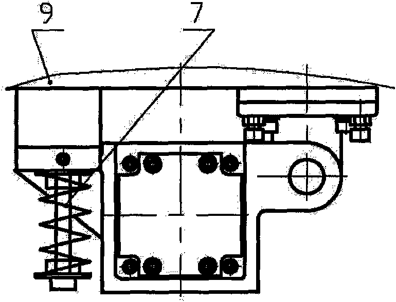
[0015] combine image 3 and Figure 4 , the positioning device for the flexible longitudinal drive mechanism proposed by the present invention includes an adjustment seat 8, whose upper and lower surfaces are all positioned with copper top wires 12, and the upper and lower top wire holes are respectively made on the upper and lower surfaces of the adjustment seat 8. The adjustment seat 8 is fixed on the large longitudinal frame 9 by the hexagon socket head cap screws. After the longitudinal gear 5 and the rack 10 of the machine are meshed to an optimal state, adjust the copper top wire 12 on the top and bottom of the adjustment seat 8 to compress the spring. There is no play gap between the top and bottom of the end 7, thereby ensuring that the gear 5 can move smoothly when ...


PUM


Abstract

The invention provides a flexible longitudinal driving mechanism positioning device, comprising an adjusting base installed on a large frame. An upper surface and a lower surface of the adjusting base are respectively provided with jackscrew holes inside which jackscrews for butting against the ends of a compression spring are arranged. The adjusting base according to the invention is fixed on the longitudinal large frame via socket cap screws, and after longitudinal rack and pinion engagement of machine is adjusted to reach an optimal state, no vertical float clearance of the ends of the compression spring is achieved by adjusting the jackscrews on the upper part and the lower part of the adjusting base, in order to guarantee that pinions can realize the steady movement of axes thereof when being engaged with longitudinal racks normally, thus the overall accuracy of machine is remarkably guaranteed in the longitudinal direction.

Description

technical field [0001] The invention relates to the field of numerically controlled flame or plasma cutting machines, and in particular to a positioning device for a flexible longitudinal drive mechanism. Background technique [0002] In the field of CNC cutting, because the working conditions of the cutting machine are generally relatively harsh, and the longitudinal dimension of the steel plate to be cut and blanked is long, the comprehensive precision of the machine is required to be high. [0003] In the prior art, the vertical and horizontal transmission systems of CNC cutting machines at home and abroad generally adopt rack and pinion transmission. The rack is fixed on the side of the guide rail, and the machine rollers roll on the guide rail. The power drives the gear to mesh with the rack on the side of the guide rail to realize the longitudinal travel of the machine. The longitudinal guide rails used are generally processed by railway guide rails, and for the conve...

Claims


Application Information

Patent Timeline
IPC IPC(8): B23K37/00B23K7/10B23K10/00
Inventor 刘小华李建强
Owner 江苏亚泰智能科技有限公司
Features
  • R&D
  • Intellectual Property
  • Life Sciences
  • Materials
  • Tech Scout
  • Unparalleled Data Quality
  • Higher Quality Content
  • 60% Fewer Hallucinations
Learn More