Hole-rolling knife

A technology of hole cutters and cutter holders, which is applied in the field of cutters for rolling round hole walls, can solve problems such as abnormal noise, poor pressure bearing capacity, and easy rotation of bearing outer rings, and achieves convenient use, high finish, and simple structure Effect

Active Publication Date: 2012-12-26
SHANDONG HAOXIN MACHINERY
View PDF0 Cites 0 Cited by
  • Summary
  • Abstract
  • Description
  • Claims
  • Application Information

AI Technical Summary

Problems solved by technology

[0002] Bearing holes on iron castings are generally obtained by machining on lathes and boring machines. Due to the high requirements for precision and surface roughness, the existing processing methods are not only difficult to guarantee the roughness requirements, but also after cutting with tools, the bearing holes The tissue compactness of the surface is also destroyed
For example: the drawing requirements for the roughness of the two bearing holes of the automobile wheel hub are very strict, and the roughness of the bearing mounting holes processed by the lathe cannot meet the drawing requirements
When the car is loaded, the outer ring of the bearing also rolls the bearing hole. Due to the low density of the surface of the bearing hole and the poor pressure bearing capacity, the size of the hub bearing hole will gradually increase under the long-term rolling effect. The outer ring of the bearing is easy to rotate in the bearing hole, causing abnormal noise during driving

Method used


Image

  • Hole-rolling knife
  • Hole-rolling knife
  • Hole-rolling knife

Examples


Embodiment Construction

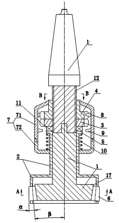
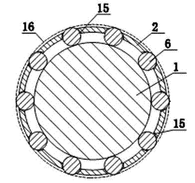
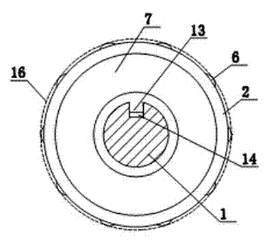
[0014] Such as figure 1 , figure 2 with image 3 As shown, the hobbing cutter includes a tool bar 1 and a tool holder 2, and an external thread 12 is provided on the middle section of the tool bar 1. The tool bar 1 is screwed with an adjusting gear 3 through the external thread 12, and an adjusting gear 3 is provided above the adjusting gear 3. The locking gear 4 whose upper end surface is in contact and can only slide axially. The locking gear 4 cooperates with the sliding key 13 fixed in its inner hole and the chute 14 provided on the cutter bar 1 to realize that the locking gear 4 can only Slide along the axial direction of the tool holder 1. The knife cover 2 is looped on the cutter bar 1 and the two are arranged concentrically. The meaning of the looper is that the knife cover 2 can rotate and slide, and a thrust bearing 11 is provided between the knife cover 2 and the adjusting gear 3 . The upper end of the knife cover 2 is provided with a shoulder 5, and the outer s...


PUM


Abstract

The invention discloses a hole-rolling knife which comprises a knife bar and a knife sheath. A regulating gear is screwed on the knife bar; the knife bar is provided with a locking gear which can only slide axially and is arranged above the regulating gear; the knife sheath is sleeved on the knife bar movably and arranged below the regulating gear; the upper end of the knife sheath is provided with a convex shoulder; a plurality of conical rollers which are embedded on the knife sheath and can slide along the radial direction of the knife sheath are annularly distributed at the lower end of the knife sheath; an included angle between the axial lead of each conical roller and the axial lead of the knife bar is the same with the self conicity of each conical roller; the knife bar is provided with a conical surface in contact with the conical rollers; a regulating sleeve is arranged outside the regulating gear and the locking gear; the inner surface of the regulating sleeve is provided with a locking tooth which can be engaged with the locking gear and a regulating tooth which can be engaged with the regulating gear; and a spring with two ends respectively pressing the convex shoulder and the regulating sleeve is externally sleeved on the knife sheath. The hole-rolling knife with the structure has the advantages of simple structure, convenient use, high surface smoothness of inner holes, high compactability of surface textures and capability of improving surface pressure bearing capacity of the inner holes.

Description

technical field [0001] The invention relates to a tool for rolling the wall of a circular hole. Background technique [0002] Bearing holes on iron castings are generally obtained by machining on lathes and boring machines. Due to the high requirements for precision and surface roughness, the existing processing methods are not only difficult to guarantee the roughness requirements, but also after cutting with tools, the bearing holes The tissue compactness of the surface is also destroyed. For example: the roughness drawings of the two bearing holes of the automobile wheel hub are very strict, and the roughness of the bearing mounting holes processed by the lathe cannot meet the requirements of the drawings. When the car is loaded, the outer ring of the bearing also rolls the bearing hole. Due to the low density of the surface of the bearing hole and the poor pressure bearing capacity, the size of the hub bearing hole will gradually increase under the long-term rolling eff...

Claims


Application Information

Patent Timeline
Patent Type & Authority Patents(China)
IPC IPC(8): B23P9/02
Inventor 孙付才牛永春金绍明
Owner SHANDONG HAOXIN MACHINERY
Why Eureka
Try Eureka