Direction indicator light mounting structure for engine driven cart

A technology for direction indicators and motorized two-wheeled vehicles, applied to bicycle accessories, transportation and packaging, optical signals, etc., can solve the problems of reduced rigidity, detachment of the cage, and increased shaking of the direction indicators, so as to improve rigidity and prevent Effects of shaking and shortening the path length

Active Publication Date: 2011-01-19
HONDA MOTOR CO LTD
View PDF7 Cites 2 Cited by
  • Summary
  • Abstract
  • Description
  • Claims
  • Application Information

AI Technical Summary

Problems solved by technology

[0004] In such a blinker installation structure, if the fitting of the retainer to the blinker bracket is too deep, a large thrust will act on the retainer when the blinker bracket deforms, so that the retainer is easy to indicate from the direction. The light bracket is detached. In addition, if the fitting of the retainer to the blinker bracket is too shallow, the rigidity of the elastic engagement part of the blinker bracket to the vehicle body will decrease, and the shaking of the blinker due to vibration will increase.

Method used


Image

  • Direction indicator light mounting structure for engine driven cart
  • Direction indicator light mounting structure for engine driven cart
  • Direction indicator light mounting structure for engine driven cart

Examples


Embodiment Construction

[0044] Hereinafter, embodiments of the present invention will be described with reference to the drawings.

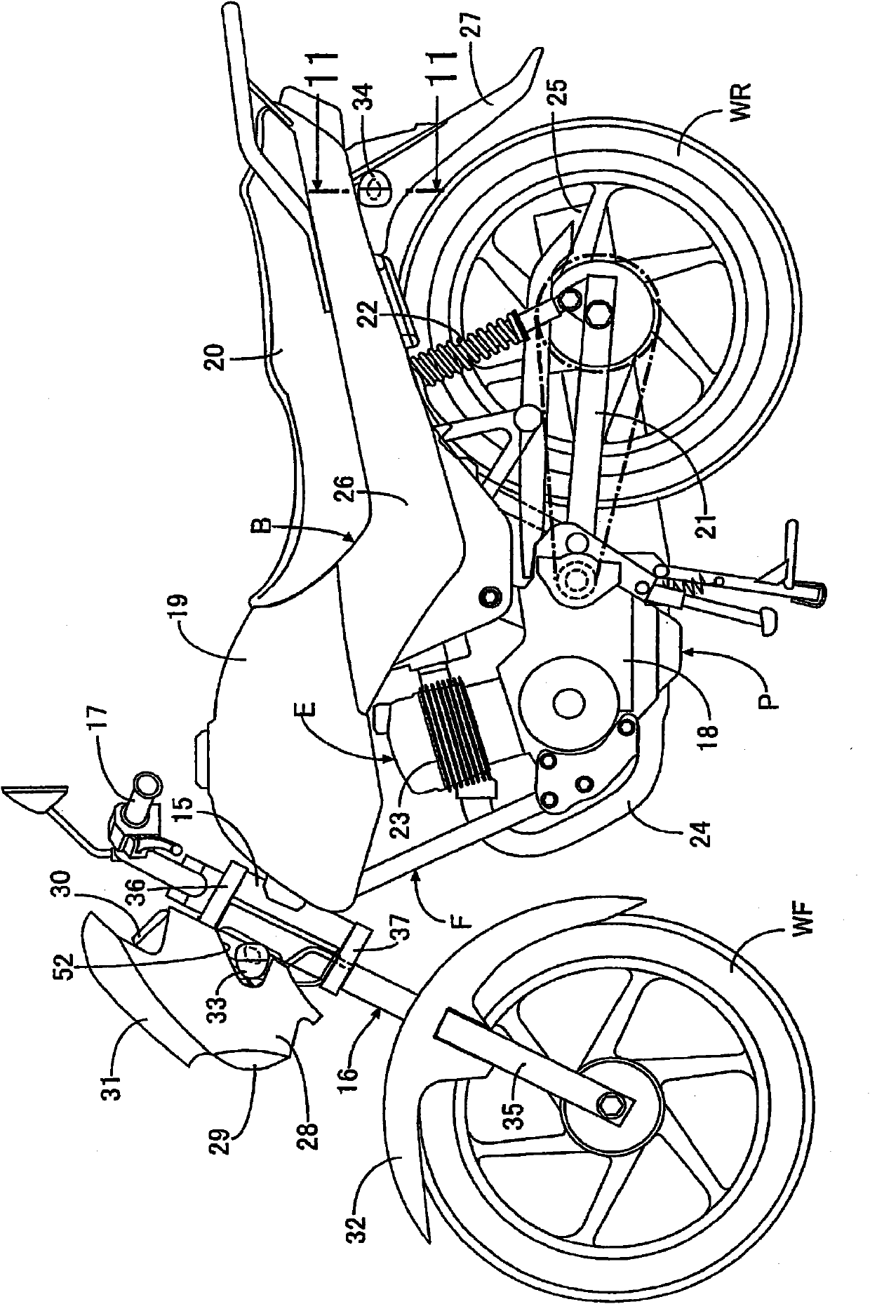
[0045] refer to Figure 1 to Figure 12 , to describe the embodiment of the present invention, first, in figure 1 Among them, a front fork 16 and a steering handle 17 are supported on the head pipe 15 provided at the front end of the body frame F of the motorcycle. The front fork 16 pivotally supports the front wheel WF. The steering handle 17 can be steered. Behind the head pipe 15 , an engine body 18 of an engine E is mounted on the body frame F, and a power unit P is constituted by the engine E and a transmission (not shown) built in the engine body 18 . Above the power unit P, a fuel tank 19 is mounted on a body frame F, and a passenger seat 20 arranged behind the fuel tank 19 is supported by the rear portion of the body frame F. As shown in FIG.

[0046] Behind the power unit P, the front end of the swing arm 21 is supported by the body frame F so that the swing a...


PUM


Abstract

The invention provides a direction indicator light mounting structure for an engine driven cart. One end of the cylinder provided with a direction indicator light rack made from flexible material is connected to the direction indicator light. The other end of the cylinder is inserted into the mounting hole on the cart and is in an elastic snap-fit with the edge of the mounting hole. A retainer isimbedded in the other end of the cylinder from the inner side of the cart body. In the direction indicator light mounting structure for the engine driven cart, the retainer is prevented from separating from the direction indicator light rack, and the rigidity of the elastic snap-fit part of the direction indicator light rack. The front end of the retainer (54) of the outer side of the cart width direction is matched with the snap-fit part of the cylinder (53a) facing the cart body (B) at the same position along the direction of the axis of the cylinder (53a).

Description

technical field [0001] The present invention relates to a direction indicator light installation structure of a motorcycle. One end of a cylinder of a direction indicator bracket formed of a flexible material is connected to the direction indicator, and the other end of the cylinder is It is inserted into a mounting hole provided in the vehicle body and elastically engaged with the periphery of the mounting hole, and a holder (holder) is fitted into the other end portion of the cylindrical portion from the inner side of the vehicle body. Background technique [0002] For example, in Patent Document 1, etc., there is known a blinker installation structure in which the blinker is mounted on the vehicle body in order to omit mounting bolts and the like, and the cylindrical portion of the blinker bracket connected to the blinker is inserted into the vehicle body. The side mounting holes are elastically engaged with the vehicle body side, and the retainer for maintaining the elas...

Claims


Application Information

Patent Timeline
Patent Type & Authority Applications(China)
IPC IPC(8): B62J6/00
Inventor 中竹顺一钱琼周越
Owner HONDA MOTOR CO LTD
Why Eureka
Try Eureka