Electromagnetic fuel injection valve

An injection valve and electromagnetic technology, applied in the direction of fuel injection devices, engine components, machines/engines, etc., can solve the problems of high processing cost, low efficiency, complex structure, etc., and achieve turbulence prevention, simple structure design, and simple design structure Effect

Inactive Publication Date: 2011-01-19
浙江冯仕特电喷技术有限公司
View PDF6 Cites 8 Cited by
  • Summary
  • Abstract
  • Description
  • Claims
  • Application Information

AI Technical Summary

Problems solved by technology

The current electronic gasoline injection valve has complex structure, high processing cost and low efficiency

Method used


Image

  • Electromagnetic fuel injection valve
  • Electromagnetic fuel injection valve
  • Electromagnetic fuel injection valve

Examples


Embodiment Construction

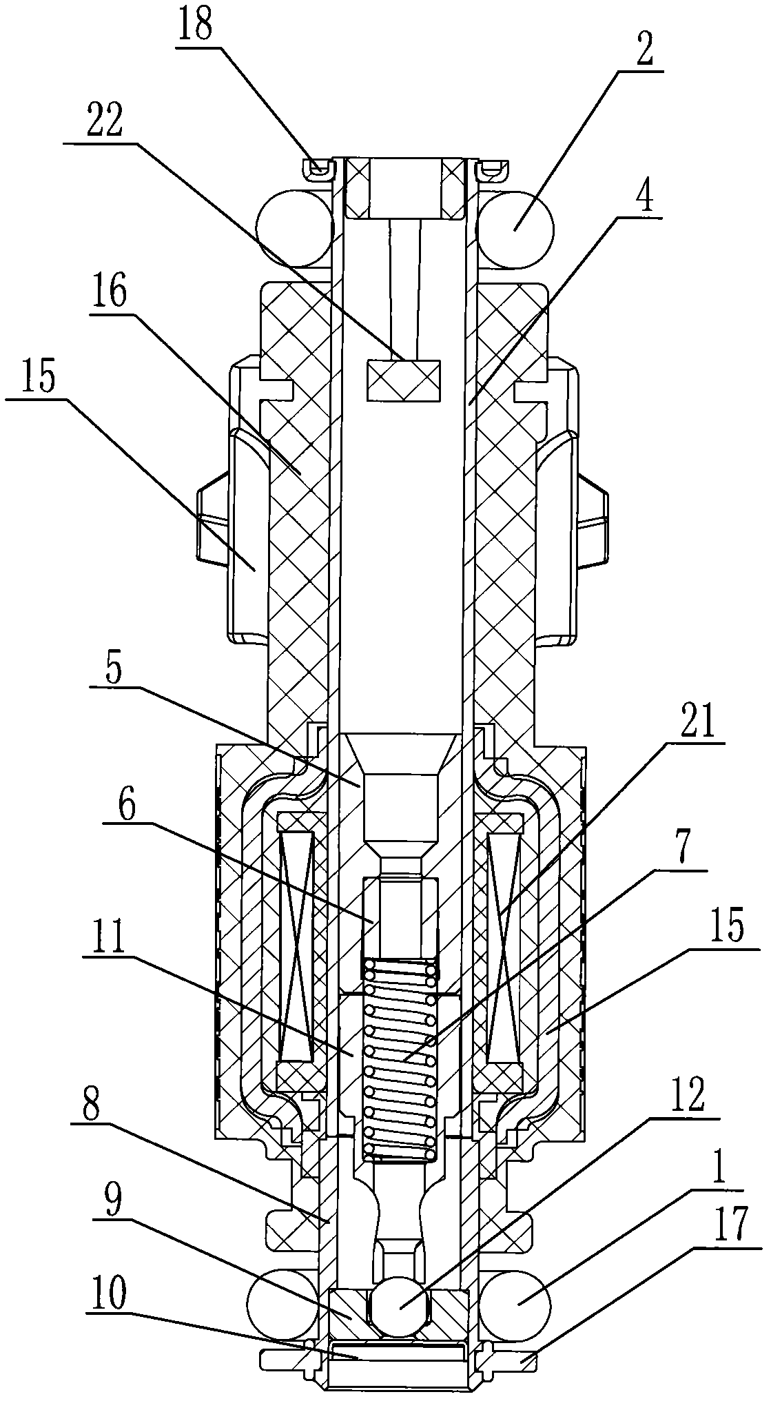
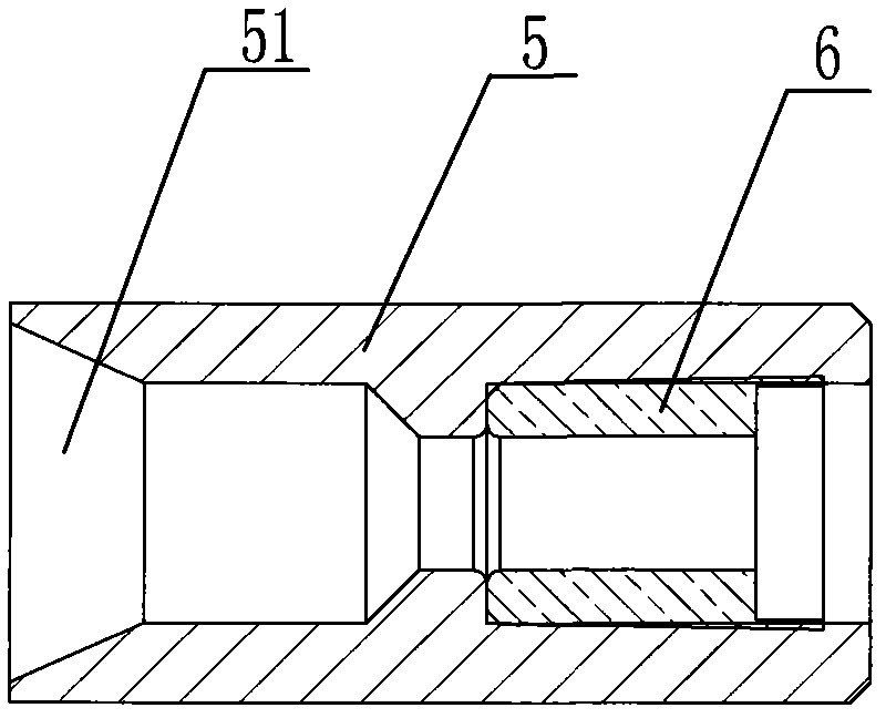
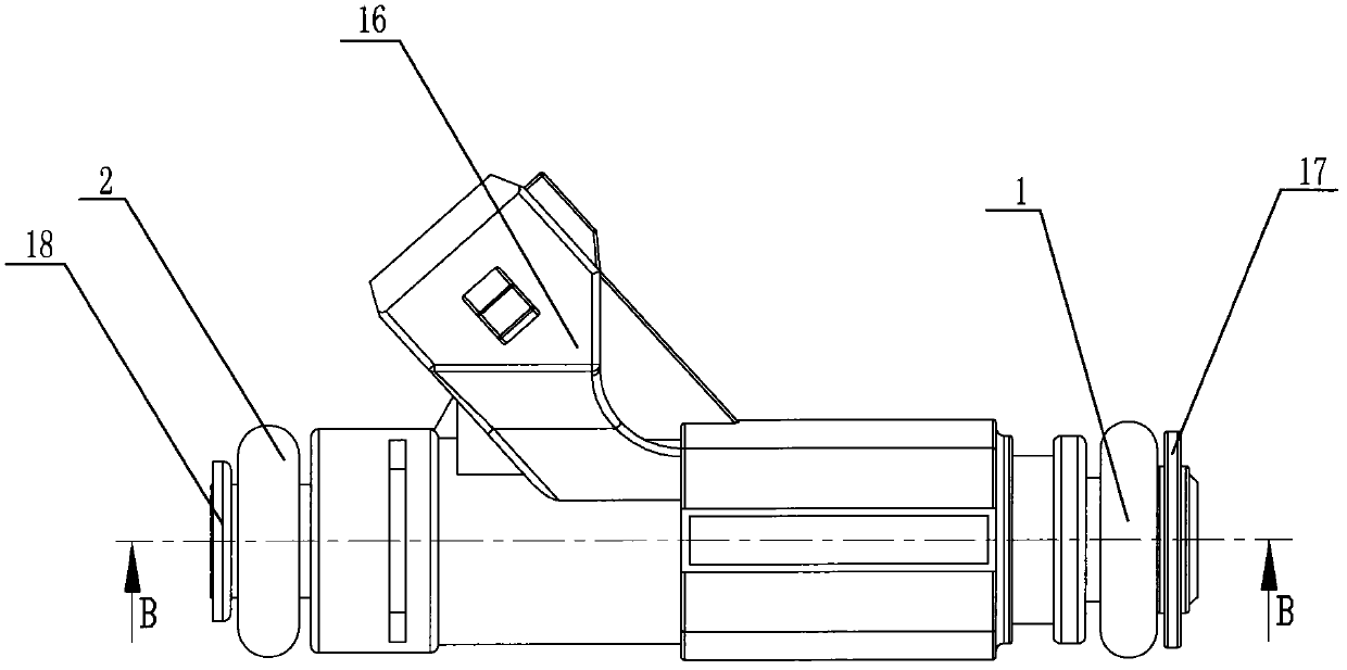
[0034] like Figure 1-12 As shown, a fuel electromagnetic injection valve includes a nozzle inlet 4, an iron core 5 is arranged inside the nozzle inlet 4, a coil 21 is wound on the iron core 5, the coil 21 is connected to an electrode sheet 14, and a spring is arranged inside the iron core 5 7. One end of the spring 7 bears against the iron core 5, and the other end bears against the magnet 11. The magnet 11 is covered with a nozzle main body 8. The nozzle main body 8 is sealed and connected with the nozzle inlet 4. The nozzle main body 8 is provided with a valve seat 9 The valve seat 9 is provided with a valve hole 20, and the front end of the magnet 11 is fixed with a steel ball 12 for closing and releasing the valve hole 20 which is matched with the valve hole 20. The iron core 5 is provided with a spring seat 6, and the spring seat 6 is provided with a stepped hole 61. One end of the spring 6 withstands the steps on both sides of the stepped hole, and the other end of the ...


PUM


Abstract

The invention discloses an electromagnetic fuel injection valve, which comprises a spray pipe inlet. An iron core is arranged in the spray pipe inlet, and a coil is wound on the iron core; the coil is connected with an electrode plate; a spring is arranged in the iron core; one end of the spring is pressed in the iron core, while the other end is pressed on a magnet; a spray pipe main body is sleeved outside the magnet; the spray pipe main body is in sealed connection with the spray pipe inlet; a valve seat is arranged in the spray pipe main body and is provided with a valve hole; and the front end of the magnet is fixed with a steel ball which is matched with the valve hole and is used for closing and opening the valve hole. The injection valve has the advantages of accurate control of oil injection, quick dynamic response, high product stability, simple structure and low processing cost.

Description

technical field [0001] The invention relates to an electromagnetic injection valve, in particular to an injection valve used in an electronically controlled gasoline engine fuel injection system. Background technique [0002] The electronic gasoline injection valve is the core component of the electronically controlled gasoline injection system of the automobile engine, which has an important influence on the combustion and emission performance of the automobile. Electronic gasoline injection valves precisely meter fuel and create a fuel spray. Due to the high requirements for the injection accuracy of oil mist, and the harsh environment such as high temperature, high pressure and vibration in the engine, the requirements for the accuracy and stability of the injection valve are very high, so the processing accuracy and production cost of the product are raised. requirements. The currently used electronic gasoline injection valve has complex structure, high processing cost...

Claims


Application Information

Patent Timeline
Patent Type & Authority Applications(China)
IPC IPC(8): F02M51/06
Inventor 冯政杰张振东程强卢学健
Owner 浙江冯仕特电喷技术有限公司
Why Eureka
Try Eureka