Translation stage capable of containing devices

A built-in translation stage technology, which is applied in the direction of instruments, optical components, installation, etc., can solve the problems of increased volume of the translation stage, difficult occasions with strict volume requirements, and large quality, so as to achieve simple mechanical transmission chain and compact structure , the effect of convenient operation

Inactive Publication Date: 2011-01-19
BEI OPTICS TECHNOLOGY COMPANY LIMITED +1
View PDF6 Cites 16 Cited by
  • Summary
  • Abstract
  • Description
  • Claims
  • Application Information

AI Technical Summary

Problems solved by technology

This type of product has a complex structure and is very bulky
[0004] Second, integrated design, the two-dimensional translation platform is designed as a whole, and the structural optimization of the entire translation platform is considered in the design. The basic design idea is that the screw rotates to drive the movement platform to move on the guide rail, and the spring provides elastic force to eliminate the gap. The volume is slightly smaller than the first solution, but the volume is still relatively large, and most of them can only be used for the adjustment of reflective opt...

Method used


Image

  • Translation stage capable of containing devices
  • Translation stage capable of containing devices
  • Translation stage capable of containing devices

Examples


Embodiment 1

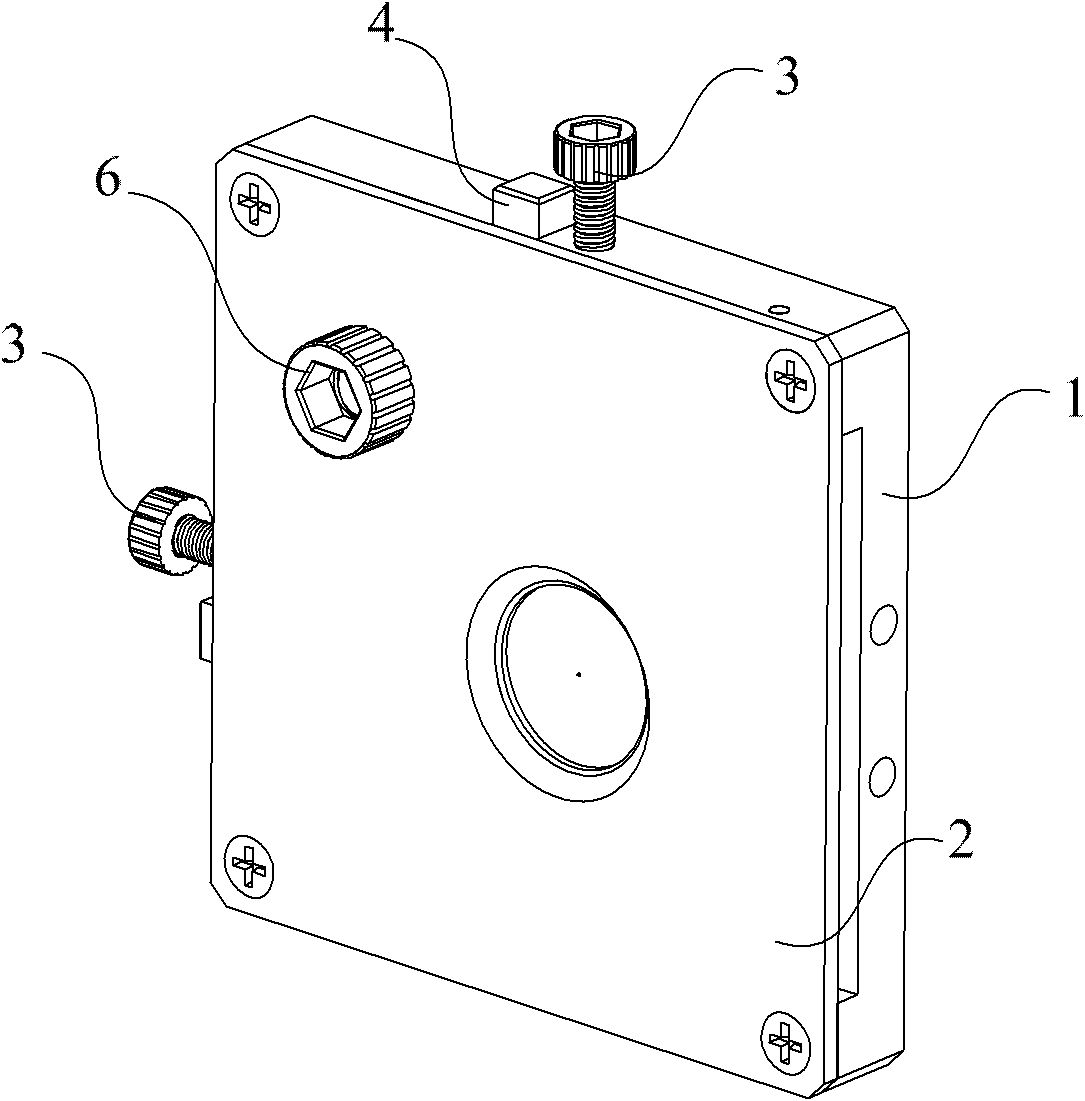
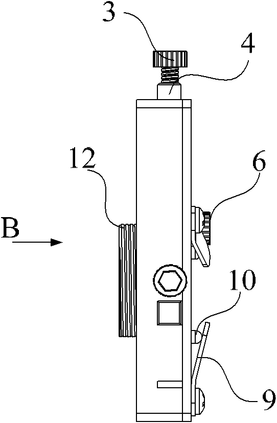
[0032] Such as figure 1 , figure 2 As shown, this embodiment provides a device-built-in two-dimensional translation platform, which is composed of a bottom plate 1 , a cover plate 2 , an adjustment bolt 3 , a push rod 4 , a spring 5 , a locking bolt 6 and a screw 8 .

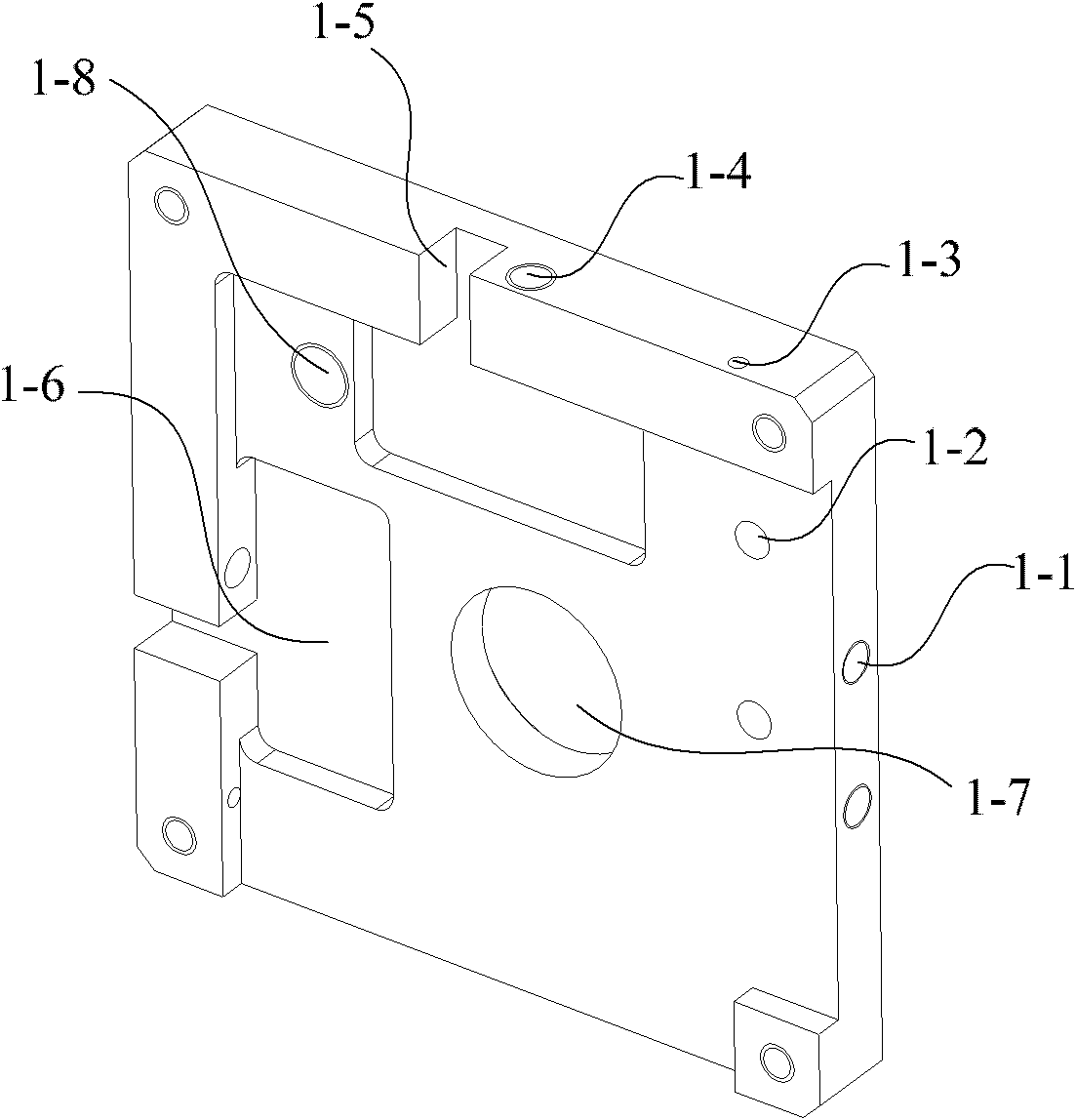
[0033] Such as figure 2 , Figure 4 As shown, the bottom plate 1 is a square plate structure, with a circular light-transmitting hole 1-7 in the middle, and a locking threaded hole 1-8 and two back mounting holes 1 on both sides of the light-transmitting hole 1-7. -2; There are side mounting holes 1-1 on the two sides of the base plate 1, and adjustment screw holes 1-4, square push rod grooves 1-5 and spring mounting holes 1-3 are provided in the middle of the other two sides of the base plate 1; There is a push rod cavity 1-6 facing the push rod groove 1-5, and the push rod groove 1-5 and the push rod cavity 1-6 constitute the movement space of the push rod 4.

[0034] Such as figure 1 , figure 2 As sh...

Embodiment 2

[0040] Such as Figure 8 As shown, this embodiment provides a three-dimensional translation platform with a built-in device. The translation platform consists of a bottom plate 1, a cover plate 2, an adjustment bolt 3, a push rod 4, a shrapnel 9, a locking bolt 6, a pressure rod 10, and a supporting plate. 11, spring 5, adjusting screw ring 12 and pin 13 are formed.

[0041] Such as Figure 8As shown, the bottom plate 1 is a square cavity structure, with screw holes 1-9 in the middle, back mounting holes 1-2, pin holes 1-10 on the bottom, adjustment screw holes, square push rod grooves, Spring mounting slot. The cover plate 2 is a square plate structure with a circular light-transmitting hole in the middle. In addition, there are three pressure rod holes 2-3 and two pin holes 2-4 on the plate. The push rod 4 is a "T"-shaped structure, and there are two push rods, which are respectively used for adjustment in two directions. There are two adjusting bolts 3, which cooperate ...


PUM


Abstract

The invention relates to the technical field of adjustment of optical devices, in particular to a translation stage capable of containing devices, which comprises a base plate and a cover plate, wherein the centers of the base plate and the cover plate are respectively provided with a round light hole, and the base plate is connected with the cover plate by a screw to form a semi-closed cavity capable of containing optical devices. By containing the optical devices in the translation stage, the invention achieves the advantages of concise mechanical drive chain, small volume, compact structure and convenient operation, thereby being very suitable for product integration or situations having stringent requirements for volume. The invention can be used for two-dimensional or three-dimensional translational adjustment of optical devices such as small pinholes, slits, lenses, reflectors and the like.

Description

technical field [0001] The invention relates to the technical field of optical device adjustment, in particular to a device built-in translation platform. Background technique [0002] Translation stages, especially two-dimensional and three-dimensional translation stages are commonly used components in optical adjustment devices. Currently, commonly used technologies include: [0003] First, a modular design is adopted to superimpose two one-dimensional translation stages to form a two-dimensional translation stage. The basic design idea of ​​each one-dimensional translation table is that the screw rotates to drive the motion table to move on the guide rail, and the spring provides elastic force to eliminate the gap. The base of another translation platform is fixedly connected on the motion platform of the first translation platform. This design solution is often bulky and can only be used for the adjustment of reflective optical devices, not for the adjustment of transm...

Claims


Application Information

Patent Timeline
IPC IPC(8): G02B7/00
Inventor 吴文镜李国光马铁中夏洋严晓浪
Owner BEI OPTICS TECHNOLOGY COMPANY LIMITED
Why Eureka
Try Eureka