Liquid crystal display device and display control method thereof

A technology of liquid crystal display devices and liquid crystal panels, which can be applied to static indicators, televisions, instruments, etc., can solve problems such as increased power consumption, image quality degradation, and large brightness attenuation, and achieve energy-saving working modes, prolong life, and reduce energy consumption. Falling effect

Inactive Publication Date: 2011-01-19
张超
View PDF4 Cites 19 Cited by
  • Summary
  • Abstract
  • Description
  • Claims
  • Application Information

AI Technical Summary

Problems solved by technology

[0002] At present, LCD TVs are developing beyond the direction of large-size display screens to meet the ever-growing high-definition video programs. Large-size display screens can display high-definition images well and bring immersive effects, but LCDs need to pass The backlight is illuminated to present images, and a large display area means that more backlights are required, which increases power consumption; but many times, such as when playing standard-definition videos and news programs, high-definition images are not required Big screens waste energy
[0003] Aiming at the above phenomenon, in Japanese Patent Documents Unexamined Publication No. 2001-142409 and No. 2006-330222, a solution is proposed in the above-mentioned patent communiqués, using a part of the area in the liquid crystal screen to display images, that is, a partial display method, instead of The backlight of the display image area is turned off, and the same solution is also proposed in my country's patent announcement number CN101645255A, but after long-term use, it will cause some backlights to age first due to long use time, and the brightness attenuation is large. When displaying images, it is easy to cause image quality degradation due to poor consistency of the backlight; in order to solve this phenomenon of uneven aging of the backlight, a new solution has emerged, see Chinese Patent Announcement No. CN 101286305A, this patent calculates different regions Accumulate the working time, and then adjust the position of the local display area next time, so that the actual use time of the backlight in each area is basically the same, so as to avoid the deterioration of image quality, but changing the position of the image is not used to the user , and the reduced image cannot always be in an optimal position

Method used


Image

  • Liquid crystal display device and display control method thereof
  • Liquid crystal display device and display control method thereof
  • Liquid crystal display device and display control method thereof

Examples


Embodiment Construction

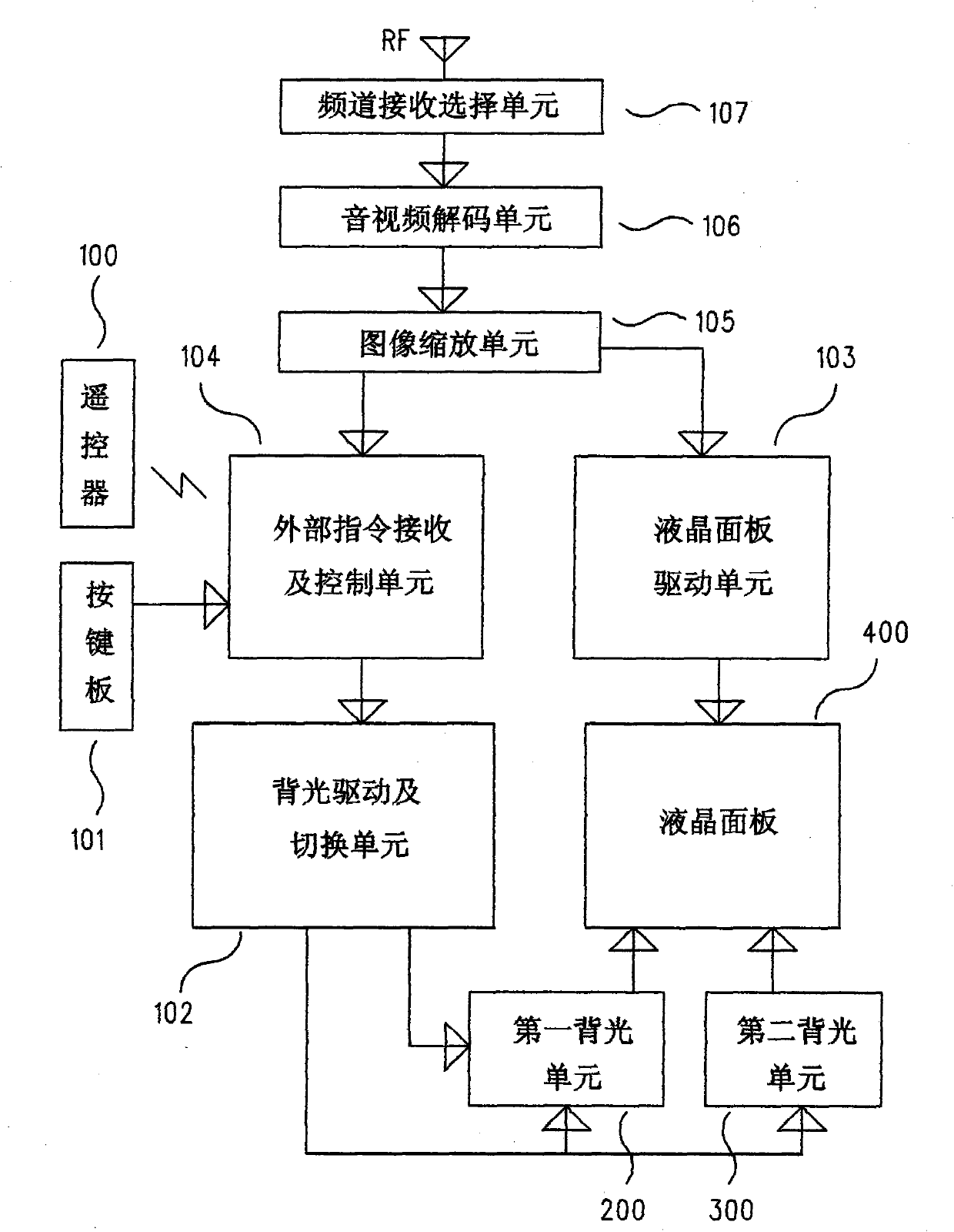
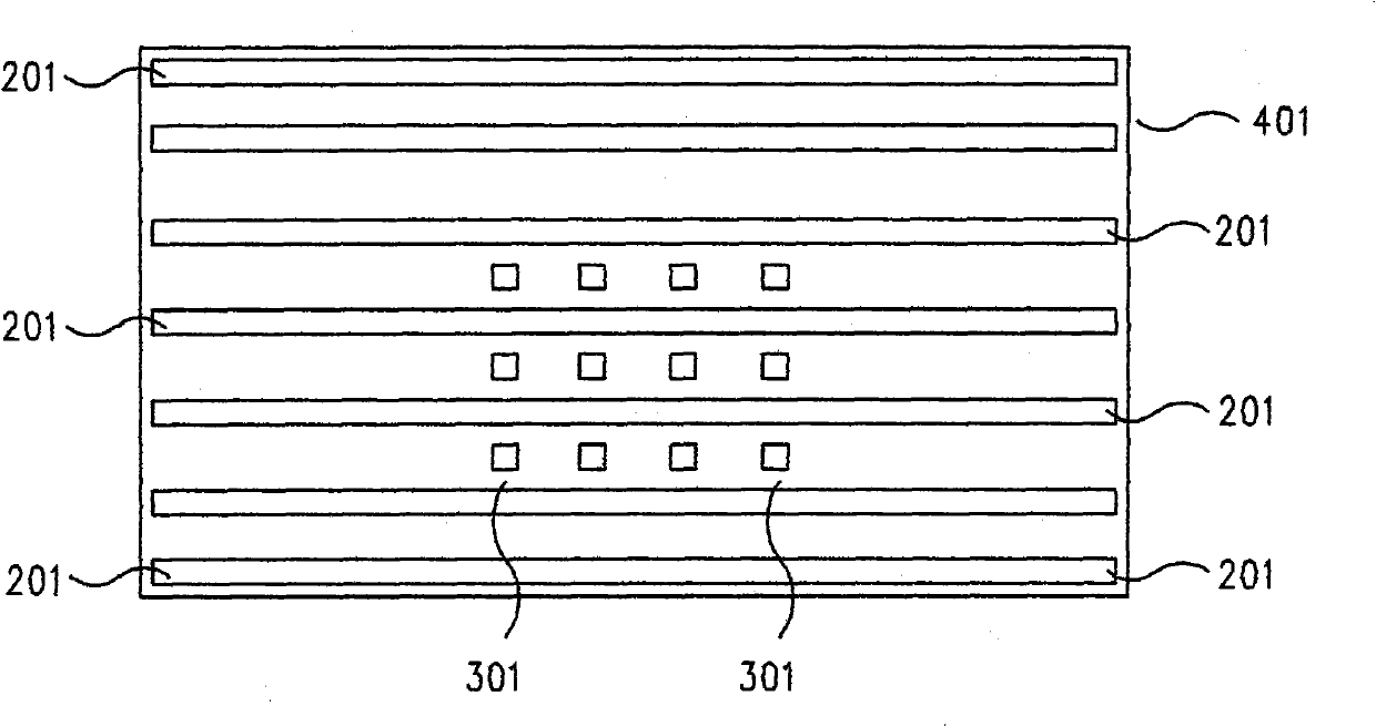
[0020] figure 1 It is the structural block diagram of the liquid crystal display device in the embodiment of the present invention, and it comprises radio frequency signal input RF; The channel receiving selection unit 107 that links to each other with RF, is used for selecting the frequency point that the user needs; To selected frequency point (channel) Audio and video decoding unit 106; The image scaling unit 105 that scales the decoded image is processed; The image after the scaling process is sent to the liquid crystal panel 103; The instruction receiving and control unit 104 and the keypad for receiving external instructions (user instructions) 101; the backlight driving and switching unit 102, used to drive (light up) the first backlight and the second backlight unit; the first backlight unit 200 corresponding to the entire screen display area; the second backlight unit 300, located in the center or partial of the entire screen In the lower area, only a corresponding su...


PUM


Abstract

The invention discloses a liquid crystal display device and a display control method thereof. The liquid crystal display device comprises a television using a liquid crystal display. Two working modes comprising a full-screen mode and an energy-saving mode are provided, wherein in the energy-saving mode, an image is zoomed out and displayed on a sub display area in a liquid crystal panel, and the sub display area is lightened by a second backlight unit; and the full-screen mode is lightened by a first backlight unit. The method realizes the energy-saving mode without affecting the consistency of backlight lamps, and can prolong the service life of the liquid crystal display device at the same time.

Description

technical field [0001] The invention relates to a liquid crystal display device, including a television using a liquid crystal display, and a display control method of the liquid crystal display device. Background technique [0002] At present, LCD TVs are developing beyond the direction of large-size display screens to meet the ever-growing high-definition video programs. Large-size display screens can display high-definition images well and bring immersive effects, but LCDs need to pass The backlight is illuminated to present images, and a large display area means that more backlights are required, which increases power consumption; but many times, such as when playing standard-definition videos and news programs, high-definition images are not required Big screens are a waste of energy. [0003] Aiming at the above phenomenon, in Japanese Patent Documents Unexamined Publication No. 2001-142409 and No. 2006-330222, a solution is proposed in the above-mentioned patent comm...

Claims


Application Information

Patent Timeline
Patent Type & Authority Applications(China)
IPC IPC(8): G09G3/36H04N5/44
Inventor 张超
Owner 张超
Why Eureka
Try Eureka