Liquid heating apparatus

A kind of equipment and liquid technology, applied in kitchen utensils, water boiling utensils, household utensils, etc., can solve problems such as not being suitable for making tea and restricting consumer appeal, and achieve the effect of increasing the overall temperature

Active Publication Date: 2011-01-19
STRIX LTD
View PDF3 Cites 12 Cited by
  • Summary
  • Abstract
  • Description
  • Claims
  • Application Information

AI Technical Summary

Problems solved by technology

The combination of these two factors means that in practice the water provided by such devices is dispensed well below boiling point, making it unsuitable for example for making tea and thus limiting its appeal to consumers

Method used


Image

  • Liquid heating apparatus
  • Liquid heating apparatus
  • Liquid heating apparatus

Examples


Embodiment Construction

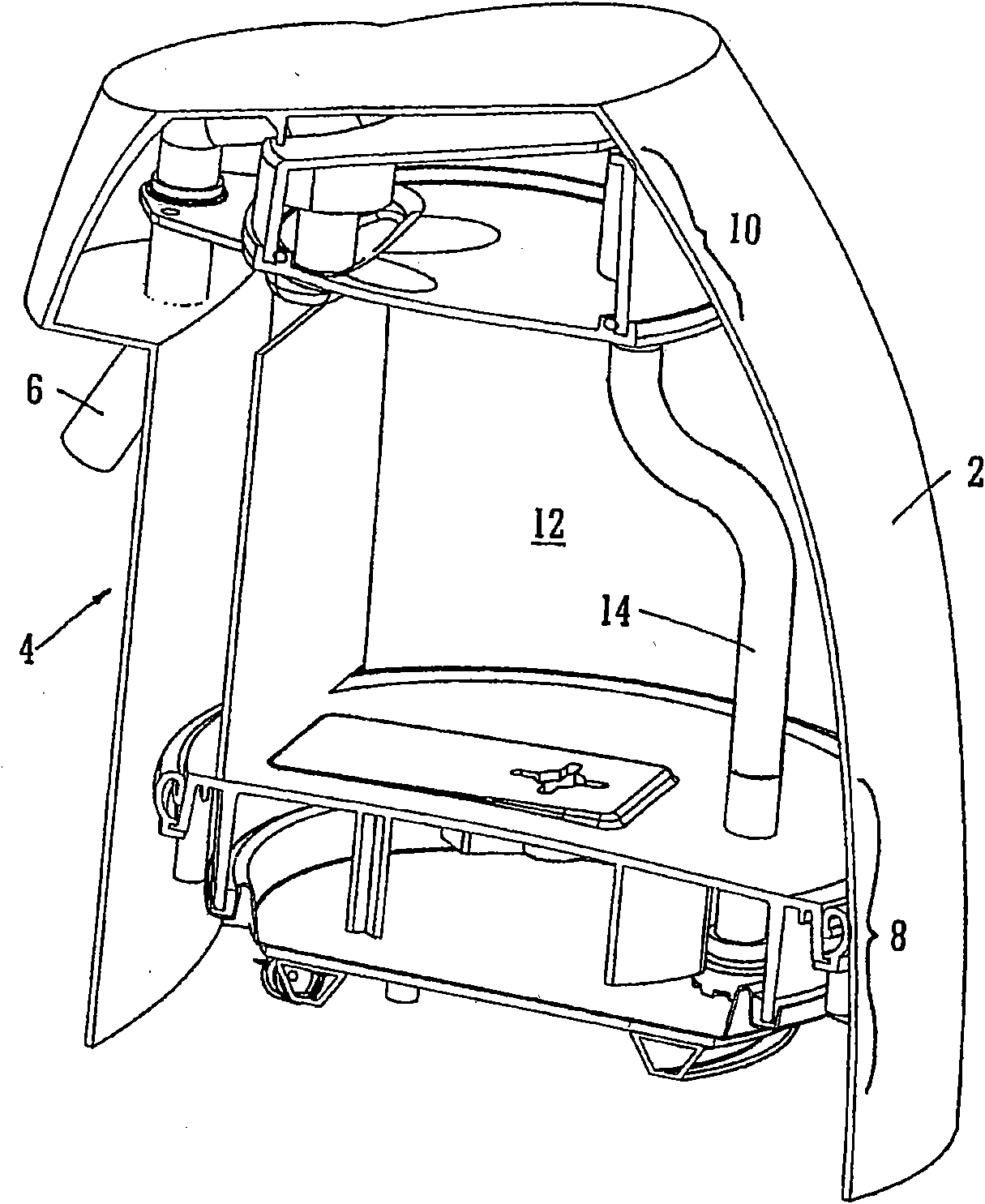
[0066] first go to figure 1 , shows a hot water dispensing container having an outer body 2 with a front "undercut" portion 4 defining a space allowing a user to place a cup or other receiving container below the outlet spout 6 . Internally, the container is divided into three main parts. In the lower part of the vessel is the heating chamber 10, which will be referred to below figure 2 and image 3 to do a more detailed description. In the upper part of the container is the dispensing chamber 10, which will be referred to below Figure 4 to do a more detailed description. Between the heating chamber 8 and the dispensing chamber 10 is a water reservoir portion 12 . This can be filled using a suitable opening (not shown) in the body. A conduit 14 passes through the water reservoir 12 and connects the heating chamber 8 to the dispensing chamber 10 .

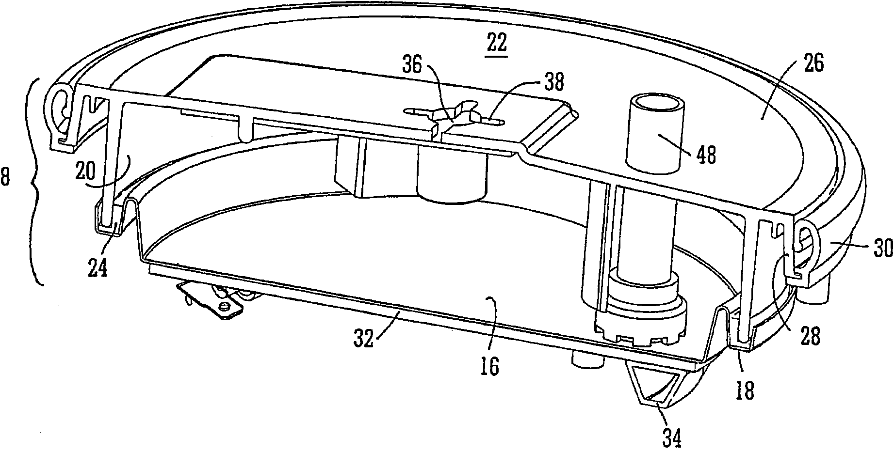
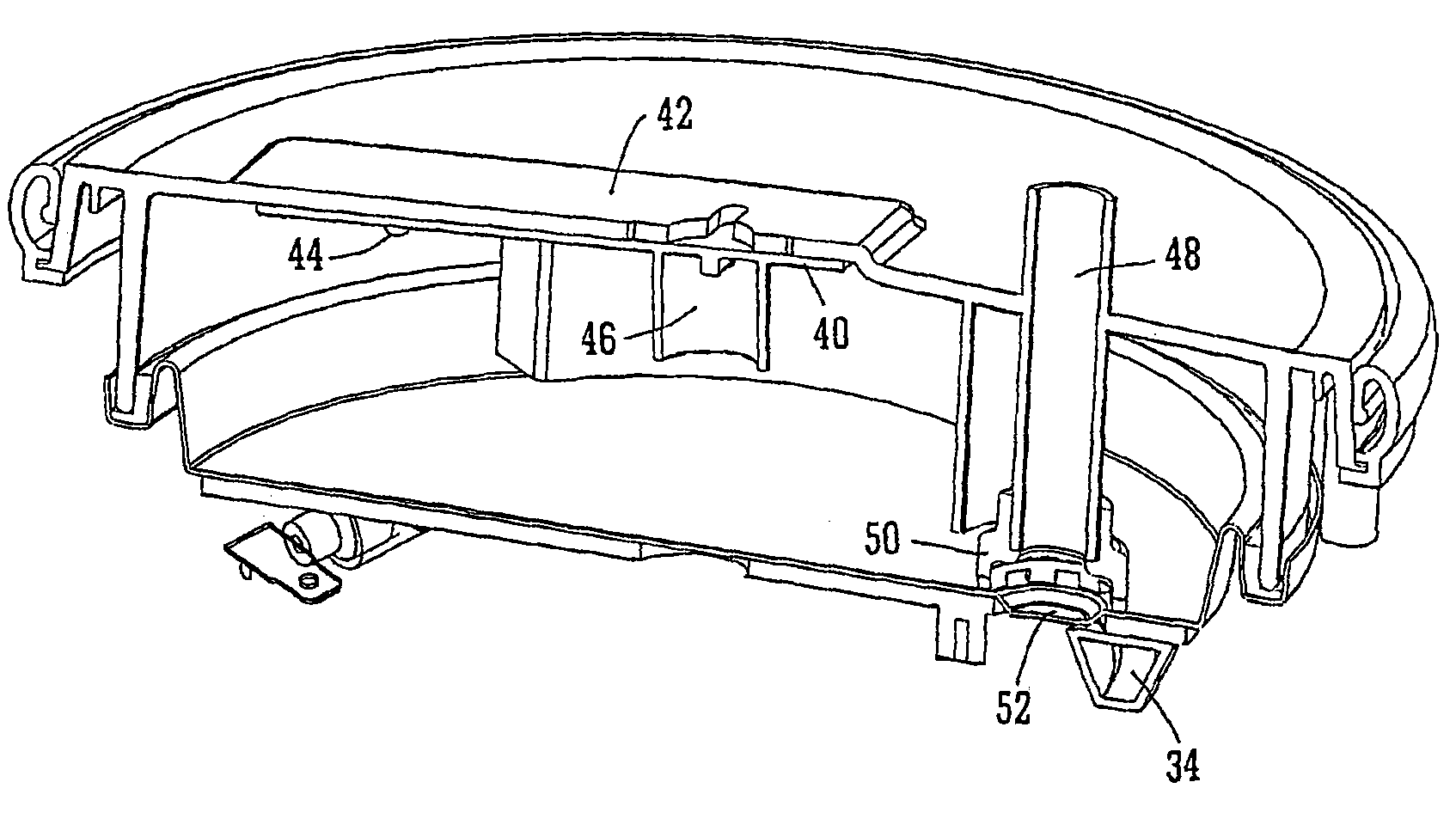
[0067] now go to figure 2 and image 3 , the heating chamber 8 can be seen in more detail. The base of the heating ch...


PUM


Abstract

An apparatus for heating a measured amount of water comprises a heating (chamber 8), a dispensing chamber (10) and a conduit for conveying water from the heating chamber to an inlet of the dispensing chamber (14). The apparatus is arranged such that an increase in pressure associated with boiling forces heated water into the conduit 14 and then into the dispensing chamber (10).

Description

technical field [0001] The present invention relates to apparatus for heating water or other liquids, and more particularly to apparatus for heating relatively small quantities of liquids in a short period of time. Background technique [0002] There is a common need to heat water for making beverages almost all over the world. In the UK and elsewhere in Europe, it is common for most households to have a kettle for boiling water for occasional beverages. In larger venues, as well as in other parts of the world, it is more common to keep a certain amount of water hot or boiling for an extended period of time - possibly throughout the day - to be able to make such Drinks that don't have to wait for water to heat up from room temperature. Examples of such devices are traditional electric kettles or more commonly known in Asia as so-called thermos bottles. [0003] Both of these devices have their disadvantages. In the case of kettles, even those using very high power (on th...

Claims


Application Information

Patent Timeline
Patent Type & Authority Applications(China)
IPC IPC(8): A47J27/21
CPCA47J27/21166
Inventor 文森特·J·加维科林·芒顿诺曼·E·尼科尔
Owner STRIX LTD
Why Eureka
Try Eureka