Exhaust bypass valve for turbocharger
一种涡轮增压器、旁通阀的技术,应用在升阀、阀装置、燃气轮机装置等方向,能够解决控制性恶化等问题,达到抑制转角变动、衰减性高的效果
- Summary
- Abstract
- Description
- Claims
- Application Information
AI Technical Summary
Problems solved by technology
Method used
Image
Examples
no. 1 approach
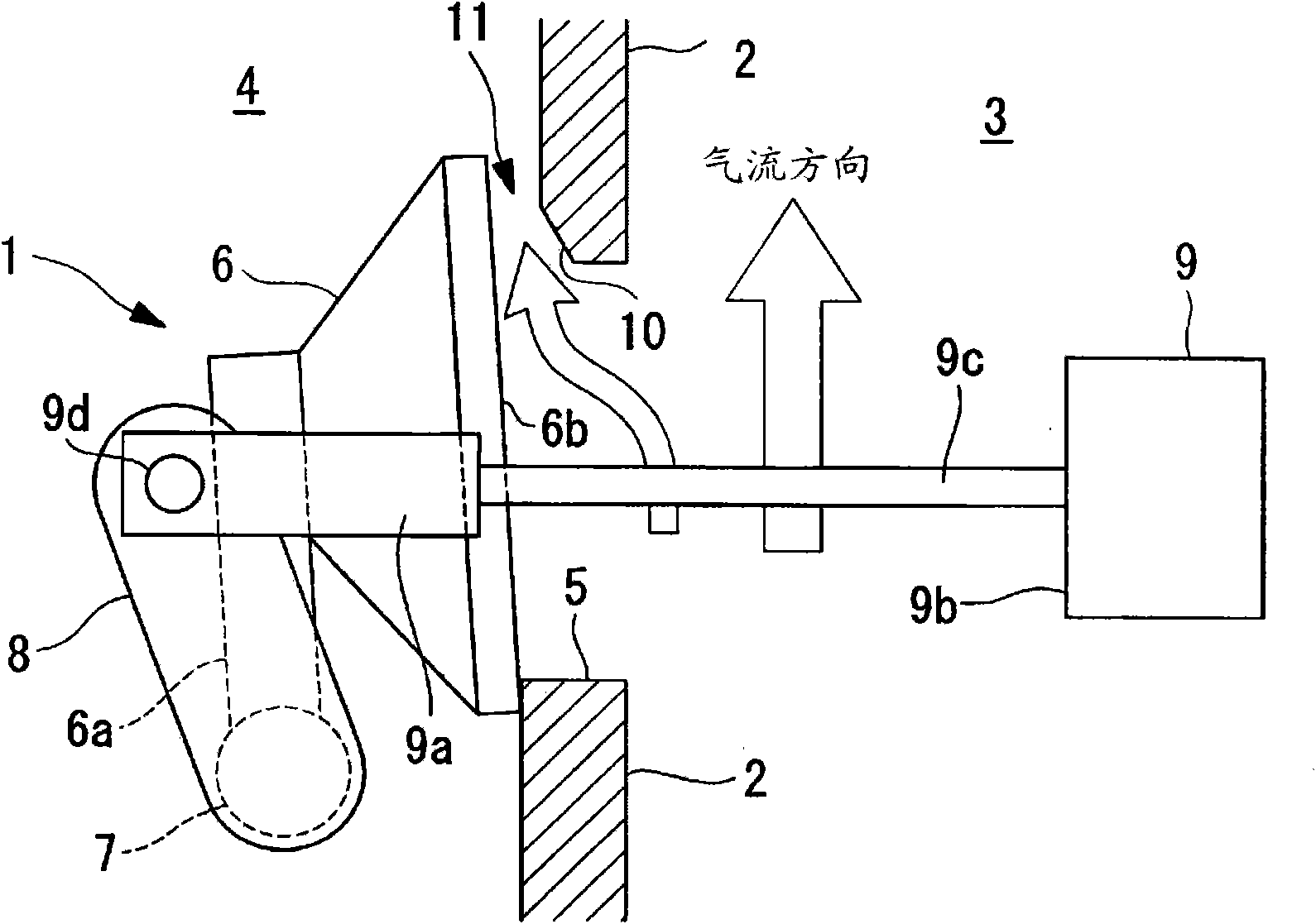
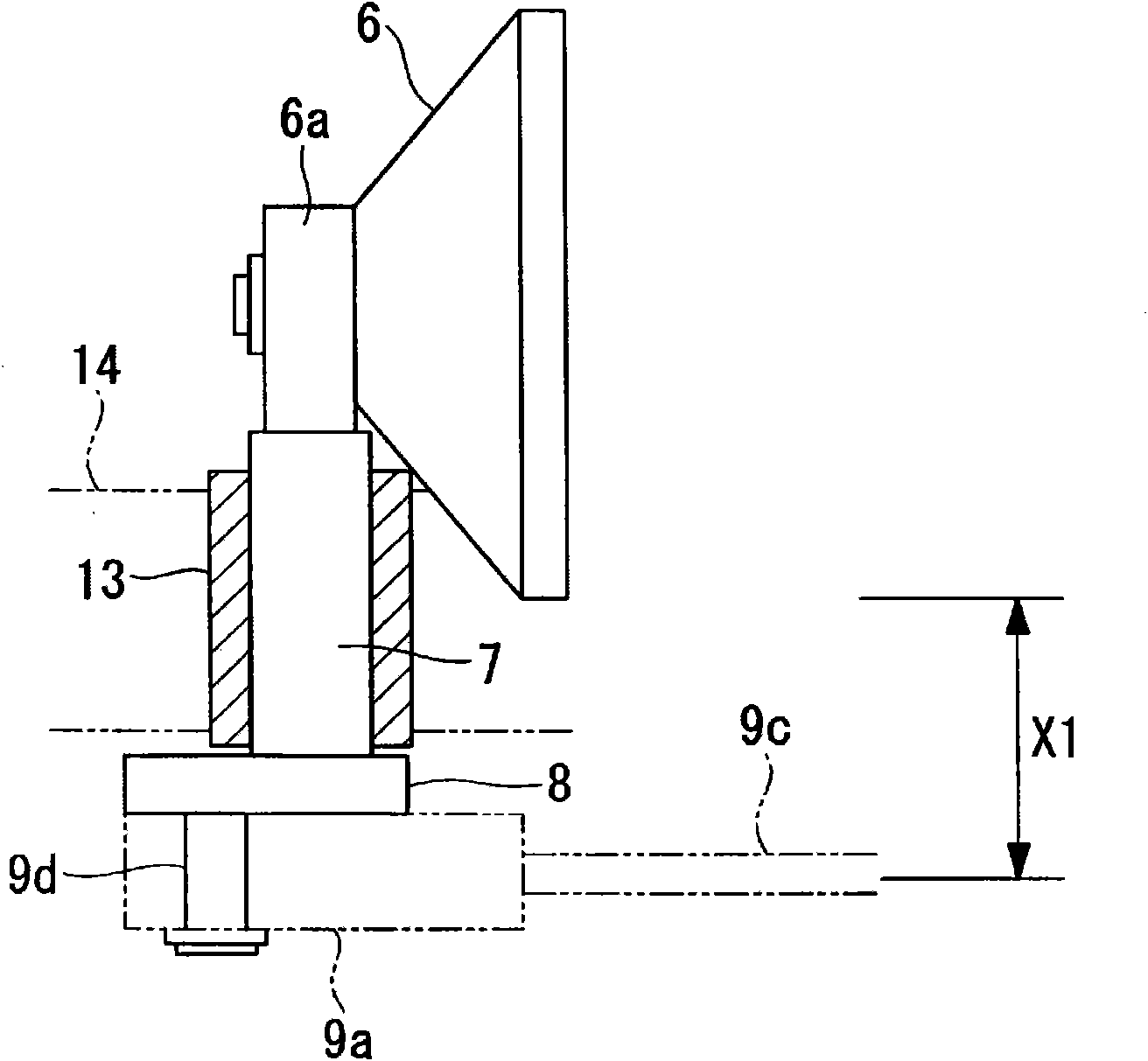
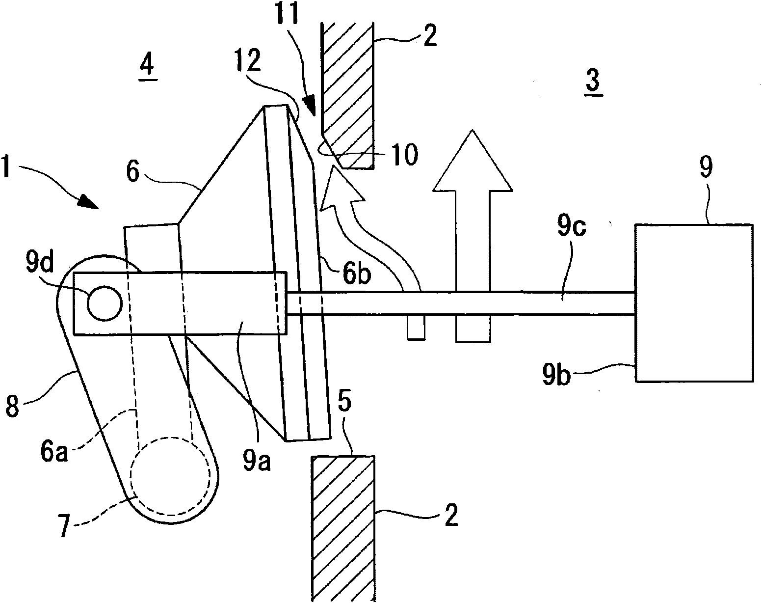
[0087] figure 1 The exhaust bypass valve 1 according to the first embodiment of the present invention is shown. figure 2 It is a plan view in which a part of the exhaust bypass valve 1 is cut away. The illustrated exhaust bypass valve 1 has a structure in which a turbine inlet-side flow path 3 and a turbine outlet-side flow path 4 separated by a partition wall 2 are short-circuited and communicated by a short-circuit flow path 5 . The exhaust bypass valve 1 has a valve flap 6 that covers the short-circuit flow path 5 in a cap-like manner. The valve flap 6 is supported by one end of an arm 6a, and the arm 6a is supported around a shaft 7 as a rotation center. One end of a rod 8 is also fixed to the shaft 7 , and the other end side of the rod 8 is driven to open and close by a driver 9 . The shaft 7 is rotatably supported by a bush 13 , and the bush 13 is fitted to a housing (fixed-side member) 14 . From figure 1 The front side of the paper faces the inner side, and the ...
no. 2 approach
[0094] Figure 5 A wastegate valve 21 according to a second embodiment of the present invention is shown. In addition, the structure of the flap 6 etc. is substantially the same as that of 1st Embodiment mentioned above, and the same code|symbol is used for the same structure, and the description is abbreviate|omitted.
[0095] In the present embodiment, the turbine inlet-side flow path 3 and the turbine outlet-side flow path 4 partitioned by the partition wall 22 are short-circuited and communicated by the short-circuit flow path 25 .
[0096] The short-circuit flow path 25 is inclined so as to approach the rotation axis center side of the shaft 7 from the turbine inlet-side flow path 3 toward the turbine outlet-side flow path 4 . As a result, a pressure increase region 30 is formed at the peripheral wall edge portion of the turbine outlet-side flow path 4 of the short-circuit flow path 25 on the side closer to the shaft 7 .
[0097] According to this structure, the short-c...
no. 3 approach
[0100] Figure 7 An exhaust bypass valve 31 according to a third embodiment of the present invention is shown. In addition, the structure of the flap 6 etc. is substantially the same as that of 1st Embodiment mentioned above, and the same code|symbol is used for the same structure, and the description is abbreviate|omitted.
[0101] In the present embodiment, the turbine inlet-side flow path 3 and the turbine outlet-side flow path 4 partitioned by the partition wall 32 are short-circuited and communicated by the short-circuit flow path 35 .
[0102] The flow passage 3 on the turbine inlet side is approximately parallel to the sealing surface 6b of the disc 6 of the exhaust bypass valve 31 in the vicinity of the exhaust bypass valve 31, and the short-circuit flow passage 35 branches off from the flow passage 3 on the turbine inlet side and flows to the outlet side of the turbine. Road 4 is short-circuited and connected. The short-circuit flow path 35 is inclined in the return...
PUM
 Abstract
Description
Claims
Application Information
 - R&D
- Intellectual Property
- Life Sciences
- Materials
- Tech Scout
- Unparalleled Data Quality
- Higher Quality Content
- 60% Fewer Hallucinations
Browse by: Latest US Patents, China's latest patents, Technical Efficacy Thesaurus, Application Domain, Technology Topic, Popular Technical Reports.
© 2025 PatSnap. All rights reserved.Legal|Privacy policy|Modern Slavery Act Transparency Statement|Sitemap|About US| Contact US: help@patsnap.com


