Relief valve

A relief valve and valve technology, which is applied in the field of relief valves, can solve the problems of unreduced construction cost, difficulty in miniaturization, complex device structure, etc., and achieve the effect of simplifying the structure, reducing the influence of valve operation, and improving productivity

Active Publication Date: 2011-01-19
JAPAN STEEL WORKS M&E INC
View PDF4 Cites 2 Cited by
  • Summary
  • Abstract
  • Description
  • Claims
  • Application Information

AI Technical Summary

Problems solved by technology

[0014] In the past, the discharge valve used in the hydrogen storage container is a spring type that adjusts the pressure release amount by changing the compression force of the spring. However, due to the complicated structure of the device, it has the following disadvantages: it is extremely difficult to miniaturize to be able to Responding to the following hydrogen storage containers that are increasingly required to be miniaturized: Hand-held or portable sizes, especially cell phone fuel cell tanks or fuel cell tanks for portable power supply equipment, etc., and the construction cost cannot be reduced

Method used


Image

  • Relief valve
  • Relief valve
  • Relief valve

Examples


Embodiment

[0060] Hereinafter, together with the drawings, preferred embodiments of the relief valve of the present invention will be described.

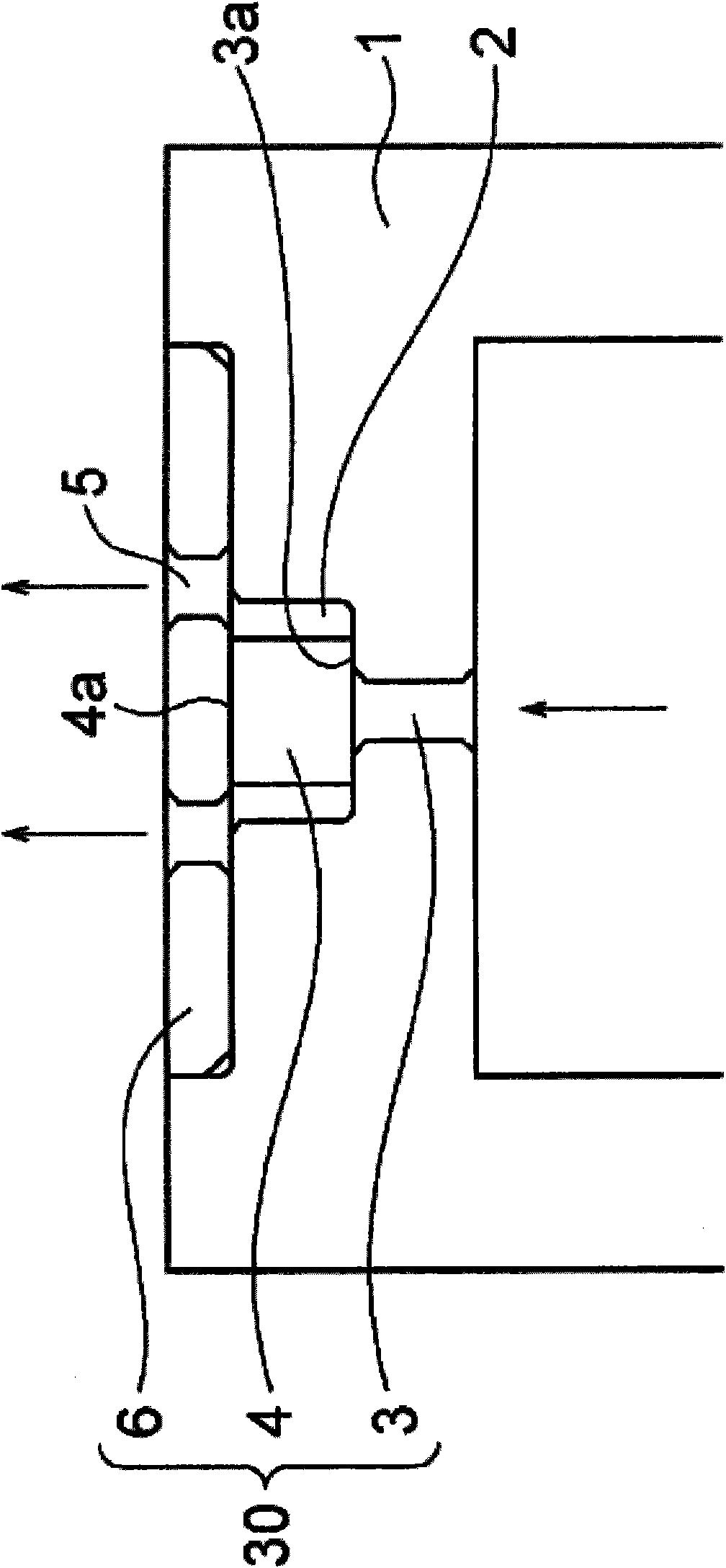
[0061] exist figure 1 Among them, the symbol 1 denotes a container with a built-in hydrogen storage alloy (not shown), and the container 1 may be a metal having appropriate strength and toughness, such as aluminum and various steels. Further, the container 1 may be an engineering plastic such as nylon that satisfies strength and toughness according to the type of gas, or a container made of a composite of plastic and metal.

[0062] A concave portion 2 is formed in the upper portion of the container 1, and a through hole 3 is formed at the bottom center of the concave portion 2. The hole 3 is provided with a rubber or the like in a state where the hole 3 is blocked. Elastomer 4 made of elastic material.

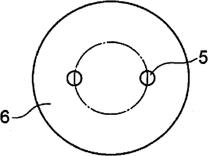
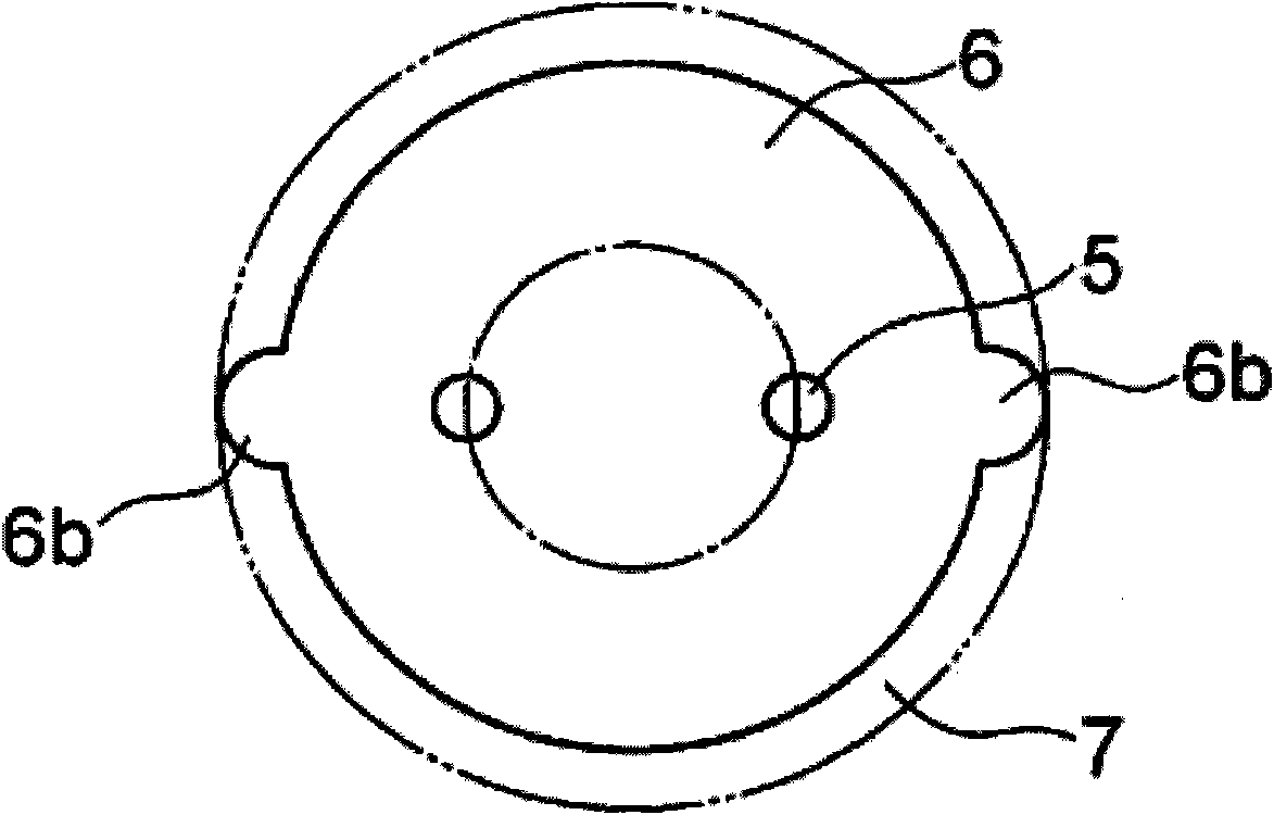
[0063] On the concave portion 2, a baffle plate 6 having a flat plate shape and having a gas release hole 5 or a groove 6c is provided in ...


PUM


Abstract

A safe valve function can be obtained by pressing an elastic body into a hole of a container containing a hydrogen storing alloy or the like. A relief valve comprises an elastic body (4) joined to a hole (3) of a container (1) and a retaining plate (6) for pressing the elastic body and has a structure in which when the pressure of hydrogen or the like in the container (1) rises, gas or the like is released to the outside from between an outer surface (3a) of the hole (3) and the elastic body (4) via an escape hole (5) for the gas or the like of the retaining plate (6).

Description

technical field [0001] The present invention relates to a relief valve, and to a new and improved technique for obtaining the function of a relief valve by extrusion disposing an elastomer into a hole of a container containing a hydrogen storage alloy, gas or liquid. Background technique [0002] Conventionally, a technology has been developed that utilizes a hydrogen storage alloy capable of storing hydrogen in low-pressure compression as a hydrogen source for hydrogen energy devices represented by fuel cells. Also, when the pressure of the hydrogen storage container rises, a device for releasing the pressure, which is used in other fields, is used as in the general pressure container. [0003] For example, a spring type relief valve is also designed to be used in hydrogen storage containers. The spring type relief valve adjusts the pressure release amount by changing the compression force on the spring. [0004] In addition, in Patent Document 1 and Patent Document 2, who...

Claims


Application Information

Patent Timeline
Patent Type & Authority Applications(China)
IPC IPC(8): F16K17/02H01M2/12H01M8/04
CPCF16K17/06Y02E60/321F16K17/02H01M2/1229H01M8/04208F16K15/14F16K17/164Y02E60/50F16K15/141H01M50/325Y02E60/10
Inventor 船津恭平佐藤幸雄河原崎芳德涉川浩一渡边阳一郎根本雅司山下武生
Owner JAPAN STEEL WORKS M&E INC
Why Eureka
Try Eureka