Hand-held power tool

一种电动工具、工具的技术,应用在机动工具、制造工具、电路等方向,能够解决大结构空间等问题,达到结构空间减少、紧凑结构、坚固力导向的效果

Active Publication Date: 2011-01-26
ROBERT BOSCH GMBH
View PDF5 Cites 10 Cited by
  • Summary
  • Abstract
  • Description
  • Claims
  • Application Information

AI Technical Summary

Problems solved by technology

Furthermore, such power tools require a huge construction space

Method used


Image

  • Hand-held power tool
  • Hand-held power tool
  • Hand-held power tool

Examples


Embodiment approach

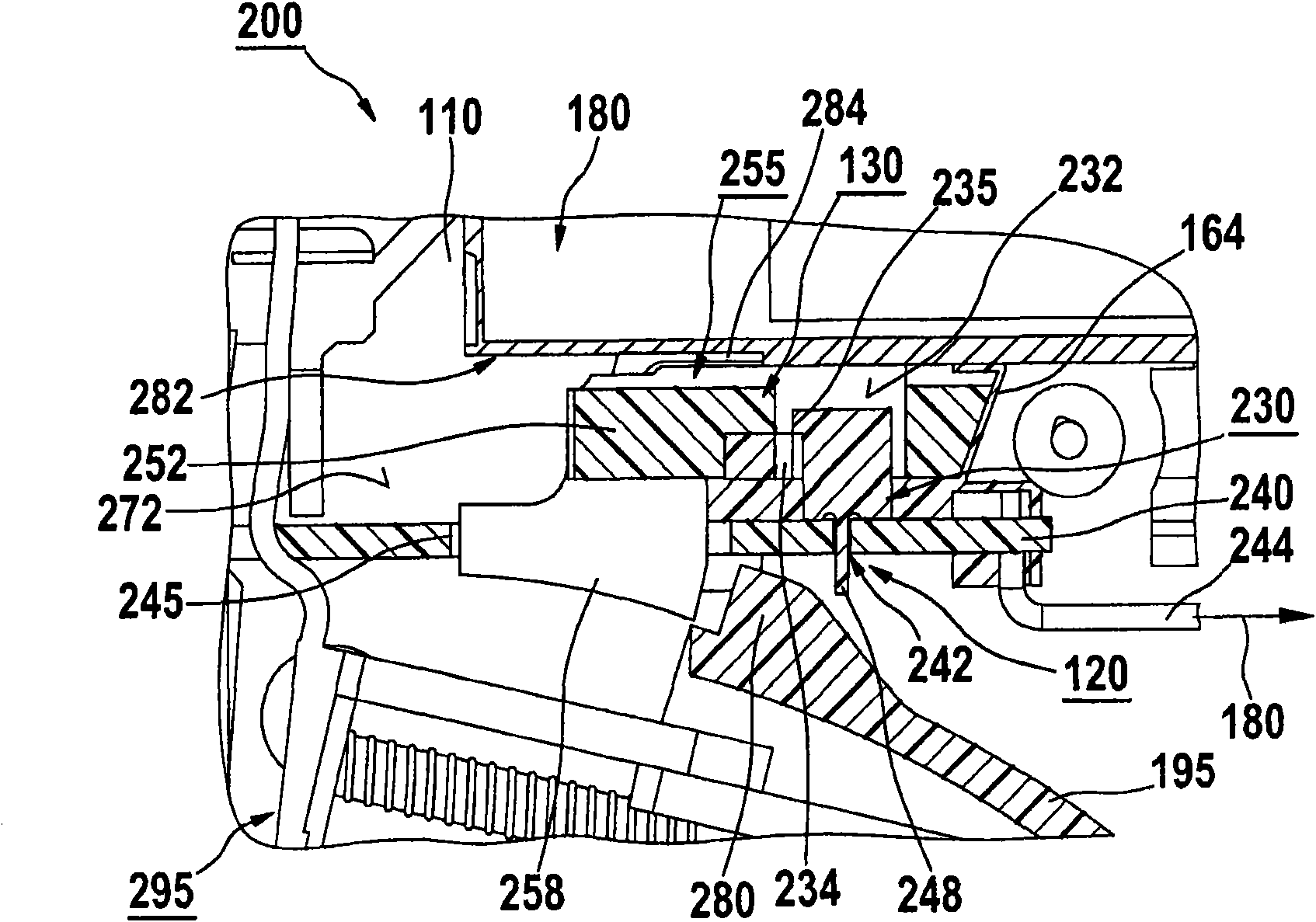
[0039]According to one specific embodiment, the switching element 230 is fastened to a printed circuit board 240 which is positioned in the tool housing 110 via suitable fastening means. The switching element 230 has, for example, a spine-shaped fastening means 248 which passes through the opening 242 of the printed circuit board 240 and is fastened to the printed circuit board 240 , for example by pressing in, gluing, soldering or wiring using SMD technology. However, it should be pointed out that the attachment of the switching element 230 to the printed circuit board 240 arranged in the tool housing 180 is not to be understood as a limiting condition of the invention. Rather, the switching element 230 can be fixed in different ways in the housing 110 , for example directly on the housing inner side 272 .

[0040] The switching element 230 is connected to the drive motor 180 or the associated motor electronics via lines 244 fastened to the printed circuit board 240 , so that...


PUM


Abstract

The invention relates to a hand-held power tool, which has a device (120) for presetting a selected rotation direction of a drive motor (180) that is associated with the power tool and contained in a tool housing (110). The device (120) is equipped with an actuating element (130) accessible from outside the tool housing (110) for mechanically actuating a switch element (110), which is situated inside the tool housing (110) and is at least embodied for electrically switching between a first and second rotation direction of the drive motor (180), the switch element (230) is situated in the vicinity of the actuating element (130).

Description

technical field [0001] The invention relates to a hand-held electric tool with a device for presetting the direction of rotation of a drive motor associated with the power tool, the drive motor being arranged in the tool housing, wherein the device has a An operating element accessible outside the housing is used for mechanically actuating a switching element which is arranged inside the tool housing and serves at least for electrically switching between a first and a second direction of rotation of the drive motor. Background technique [0002] Hand-held power tools of this type are known from the prior art, in which the respective operating element is connected to a suitable switching element via an associated transfer element. The transmission element is usually a guide rod with which the actuation result of the operating element is mechanically transmitted to the associated switching element. [0003] A disadvantage of the prior art is that the link generally has only l...

Claims


Application Information

Patent Timeline
Patent Type & Authority Applications(China)
IPC IPC(8): B25F5/00B25B21/00
CPCB25B21/00B25F5/00B25F5/001H01H9/063
Inventor J·韦尔克D·索尔
Owner ROBERT BOSCH GMBH
Why Eureka
Try Eureka