Embedded compound spinning frame and spinning method thereof

A compound spinning and spinning frame technology, applied in the field of spinning, can solve problems such as difficult to spin high-count yarn and ultra-high-count yarn, short fiber waste, difficult to spin short fiber or ultra-short fiber yarn, etc.

Inactive Publication Date: 2011-01-26
DONGFEI MAZUOLI TEXTILE MACHINERY +1
View PDF6 Cites 7 Cited by
  • Summary
  • Abstract
  • Description
  • Claims
  • Application Information

AI Technical Summary

Problems solved by technology

Therefore, the existing ring spinning equipment and technology are not only difficult to spin high-count yarn and ultra-high-count ya

Method used


Image

  • Embedded compound spinning frame and spinning method thereof
  • Embedded compound spinning frame and spinning method thereof
  • Embedded compound spinning frame and spinning method thereof

Examples


Embodiment Construction

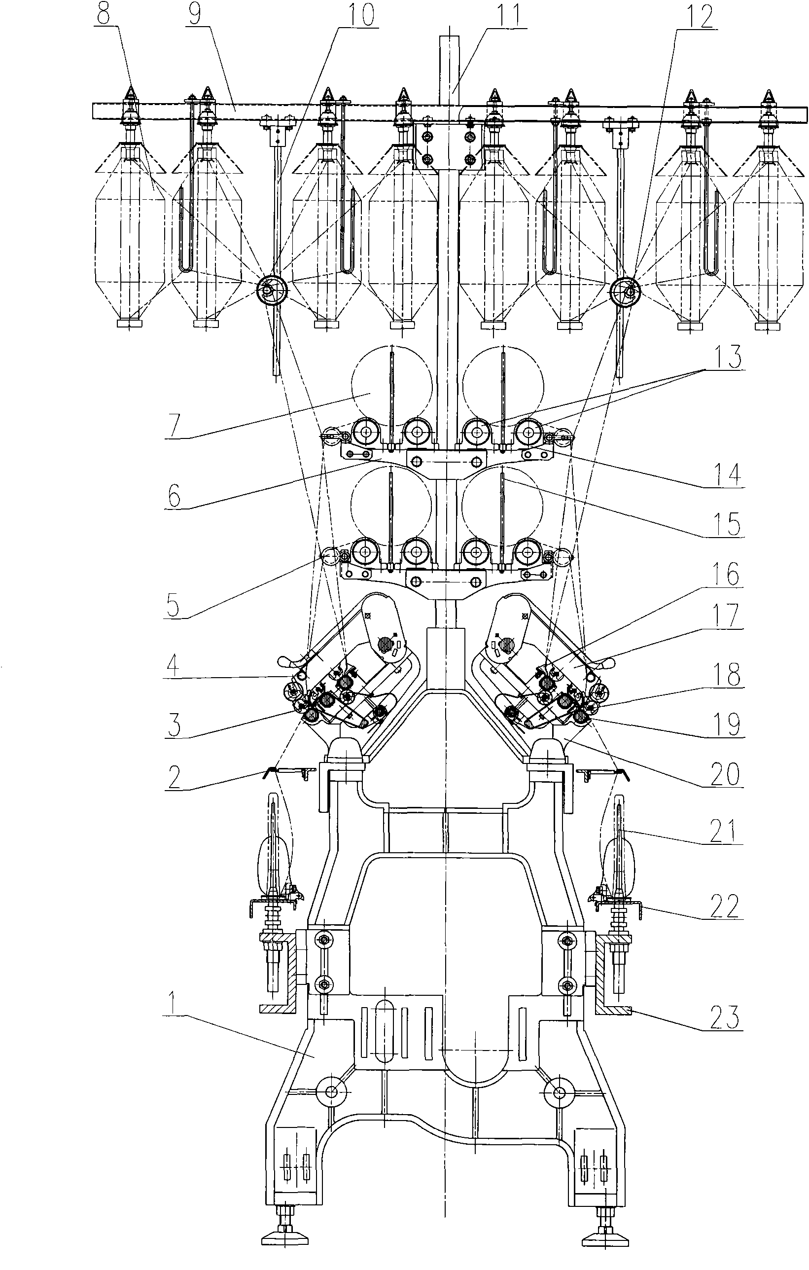
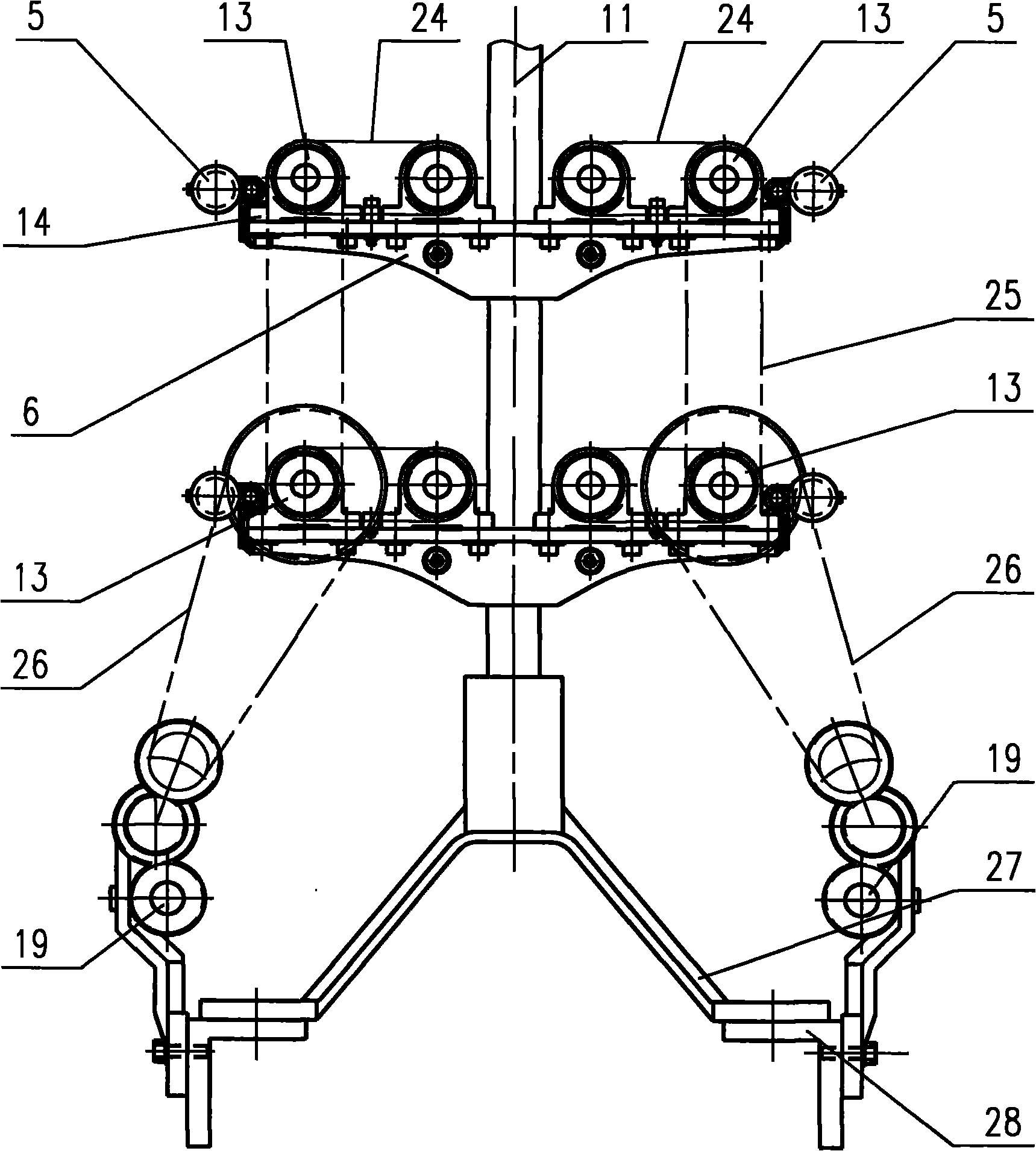
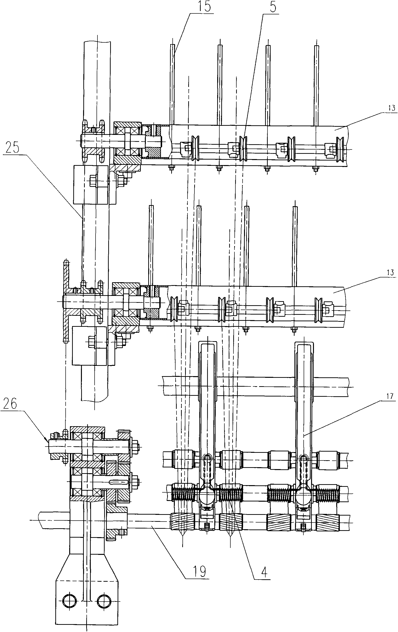
[0014] figure 1 The shown embedded composite spinning frame includes a frame composed of a wall panel 1, a dragon rib 23, a beam 28, etc., and a drafting mechanism 3 and a roving frame column 11 installed on the frame. A roving frame 9 for suspending the roving 8 is installed at the upper end of the roving frame column 11. The roving frame 9 adopts a single-layer 8-row structure. A yarn guide rod 12 is installed on the lower side of the roving frame 9 through a guide rod support 10. Two layers of unwinding brackets 6 are installed from top to bottom in the middle section of the roving frame column 11. Each layer of unwinding bracket 6 is equipped with four unwinding supports 14 arranged in parallel along the length of the spinning frame. The unwinding roller 13, the upper and lower unwinding brackets 6 and the unwinding roller 13 on the upper and lower layers have the same structural form. The two unwinding rollers 13 on the same side of the roving frame column 11 support filame...


PUM


Abstract

The invention discloses an embedded compound spinning frame. Two layers of unwinding brackets and four parallel unwinding rollers are arranged on an upright post of a creel; the unwinding rollers positioned on the same side of the unwinding brackets mutually drive and are connected by a vertical driving pair of the unwinding rollers; and at least one unwinding roller in the unwinding rollers on the same side of the unwinding brackets is in driving connection with a front roller of a drawing mechanism through an unwinding roller driving device. When in spinning, two rovings hung on the creel respectively enter a drawing area of the drawing mechanism in parallel through roving horn mouths for drawing; two unwound filaments roll from different unwinding rollers and respectively enter the rear side of a tong port of the front roller of the drawing mechanism through a filament guider; and the two filaments and two drawn rovings are combined on the rear side of the tong port of the same front roller, output and twisted from the front side of the tong port of the front roller and wound on a spinning tube of a spindle. The invention not only can conveniently spin short fibers and other low-grade raw materials, but also has the advantages of abundant yarn type structures, dry resultant slivers and superior filoplume indexes.

Description

Technical field [0001] The present invention relates to the technical field of spinning, in particular to a ring spinning frame for realizing embedded composite spinning. The invention also relates to a spinning method using the ring spinning machine for spinning. Background technique [0002] The ring spinning frame is the key equipment for the spinning process. The traditional ring spinning frame mainly includes a feeding mechanism, a drafting mechanism and a twisting and winding mechanism installed on the frame; the feeding mechanism is mainly composed of a roving frame and a yarn guide rod. And traverse devices; the drafting mechanism is mainly composed of a pressure cradle and three pairs of front, middle and rear rollers; the twisting and winding mechanism is to guide the strands output from the jaws of the front roller of the drafting mechanism in turn Yarn hooks, steel rings, travellers, and the bobbin mounted on the spindle are twisted into spun yarn. [0003] Due to the...

Claims


Application Information

Patent Timeline
IPC IPC(8): D01H1/02D01H1/18
Inventor 朱鹏高翔卜仁佺何梅何艳萍
Owner DONGFEI MAZUOLI TEXTILE MACHINERY
Why Eureka
Try Eureka