Non wire drawing type electronic throttle control method

An electronic throttle and control method technology, applied in the direction of engine control, machine/engine, mechanical equipment, etc., can solve the problems of short service life, easy damage, affecting the reliability and safety of the electronic throttle control system, and improve safety. and comfort effects

Active Publication Date: 2011-01-26
SHANXI GUOLI INFORMATION TECH
View PDF6 Cites 2 Cited by
  • Summary
  • Abstract
  • Description
  • Claims
  • Application Information

AI Technical Summary

Problems solved by technology

[0005] Existing throttle position sensors mostly adopt the resistance detection method of potentiometer structure. The throttle position sensor with potenti

Method used


Image

  • Non wire drawing type electronic throttle control method
  • Non wire drawing type electronic throttle control method
  • Non wire drawing type electronic throttle control method

Examples


Embodiment Construction

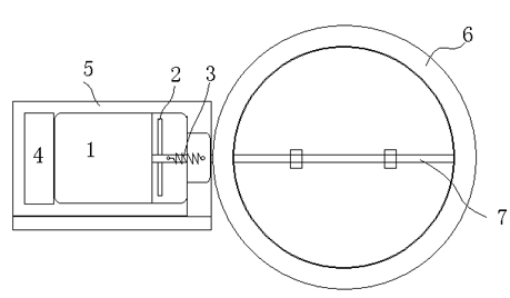
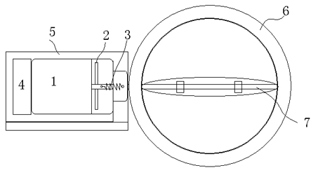
[0020] Such as figure 1 As shown, the cable-free electronic throttle control method includes at least: a motor 1, an angle sensor, a return spring 3, a controller 4, a throttle valve 6, a throttle control shaft 7 of the throttle valve 6, and a throttle valve of the throttle valve 6. The control shaft 7 is connected coaxially with the output shaft 10 of the motor 1, and the differential capacitive angle sensor 2 is connected between the throttle control shaft 7 and the output shaft 10 of the motor 1, and the two fixed electrodes of the differential capacitive angle sensor 2 The sheet 9 is fixed to the housing 5, and a moving electrode sheet 8 of the differential capacitive angle sensor 2 is fixed to the output shaft 10 of the motor 1. After the controller 4 receives the throttle control command, it The capacitance control motor 1 of the capacitive angle sensor 2 makes the throttle control shaft 7 rotate, as figure 2 shown.

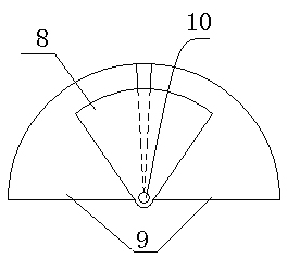
[0021] Such as image 3 with Figure 4 As shown,...


PUM


Abstract

The invention relates to a throttle control technology, in particular to a non wire drawing type electronic throttle control method. An electronic throttle control system at least comprises a motor, an angular transducer, a return spring, a controller, a throttle valve and a throttle control shaft of the throttle valve. The electronic throttle control method is characterized in that the throttle control shaft of the throttle valve is coaxially connected with an output shaft of the motor; the angular transducer connected between the throttle control shaft and the motor is a differential capacitance type angular transducer, two fixed electrode plates of the differential capacitance type angular transducer are fixed on a case, and one moving electrode plate of the differential capacitance type angular transducer is fixed with the output shaft of the motor; and after the controller receives a throttle control command, the controller controls the motor to rotate the throttle control shaft according to the command of the controller and the capacitance of the differential capacitance type angular transducer. The non wire drawing type electronic throttle control method has the advantages of long service life, safety and reliability.

Description

technical field [0001] The invention relates to throttle control technology, in particular to a cable-free electronic throttle control method. Background technique [0002] Due to various reasons such as environmental protection, economy, reliability, etc., newer models now generally use electronic accelerators. The so-called electronic accelerators are aimed at the previous pull-wire accelerators. The traditional pull-wire accelerators directly connect the accelerator pedal to the The solar terms are connected, and the depth of the accelerator pedal directly corresponds to the opening and closing of the solar terms. [0003] The characteristic of the traditional pull-wire accelerator is that the system is simple, the control is direct, and the opening of the accelerator pedal and the throttle is 1:1; while the characteristic of the electronic accelerator is that the accelerator pedal only represents the driver's operation intention, and the final control of the throttle is ...

Claims


Application Information

Patent Timeline
IPC IPC(8): F02D11/10
Inventor 曾卫东潘亚敏
Owner SHANXI GUOLI INFORMATION TECH
Why Eureka
Try Eureka