
Constant-speed universal coupling

A technology of universal joints and shaft couplings, which is applied in the direction of shaft couplings, elastic couplings, mechanical equipment, etc., can solve the problems of small angle, complex structure, large radial size, etc., and achieve the effect of simple structure

Inactive Publication Date: 2011-01-26
陈用毅
View PDF3 Cites 5 Cited by
  • Summary
  • Abstract
  • Description
  • Claims
  • Application Information

AI Technical Summary

Problems solved by technology

However, the Thompson coupling has a small transmission angle, complex structure, large radial size, and the diameter of one of the main and driven shafts is too small, which limits the load it can transmit.
[0007] The couplings mentioned above cannot simultaneously have the advantages of pure rolling transmission without sliding friction, constant speed transmission, large-angle transmission, heavy-duty transmission, ability to bear axial and radial loads and simple structure

Method used


Image

  • Constant-speed universal coupling
  • Constant-speed universal coupling
  • Constant-speed universal coupling

Examples


Embodiment Construction

[0050] Four embodiments of the present invention will be described below. The constant speed transmission referred to in this manual means that the instantaneous rotational speed of the main and driven shafts of the coupling is equal at any moment. Figure 5 It is a brief diagram of terms related to the present invention, wherein the supplementary angle bisector (83) between the driving shaft (80) and the driven shaft (81) is defined as: between the driving shaft (80) and the driven shaft (81) The angle bisector of the supplementary angle (85) of the included angle (84). The plane of symmetry (82) between the driving shaft (80) and the driven shaft (81) is defined as: the plane that can make the driving shaft (80) and the driven shaft (81) symmetrical. The slewing pairs of all embodiments in the accompanying drawings in this specification are sliding friction. In order to realize pure rolling transmission, rolling bearings can be used in these slewing pairs, such as ball bear...


PUM


Abstract

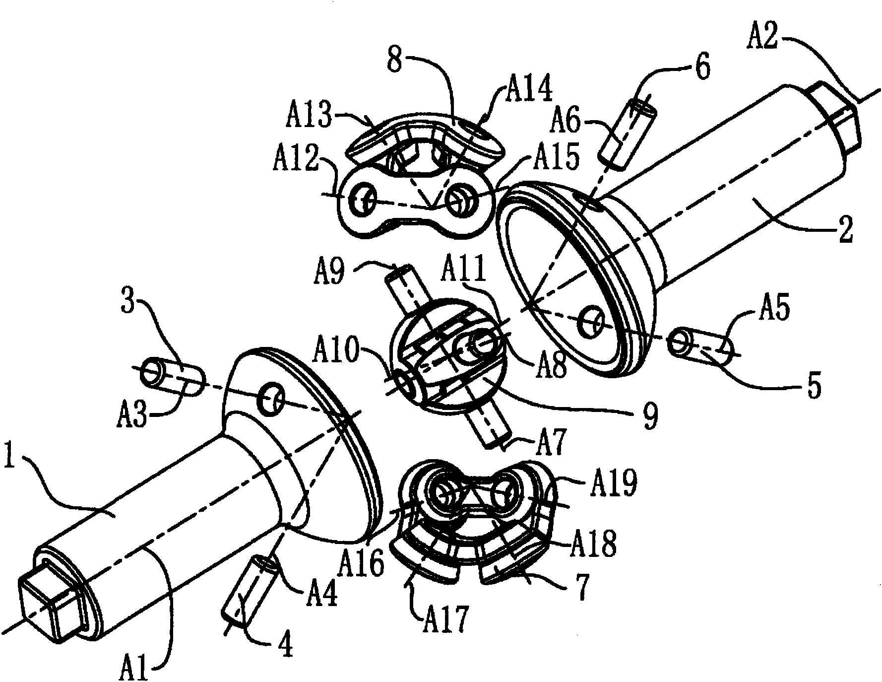
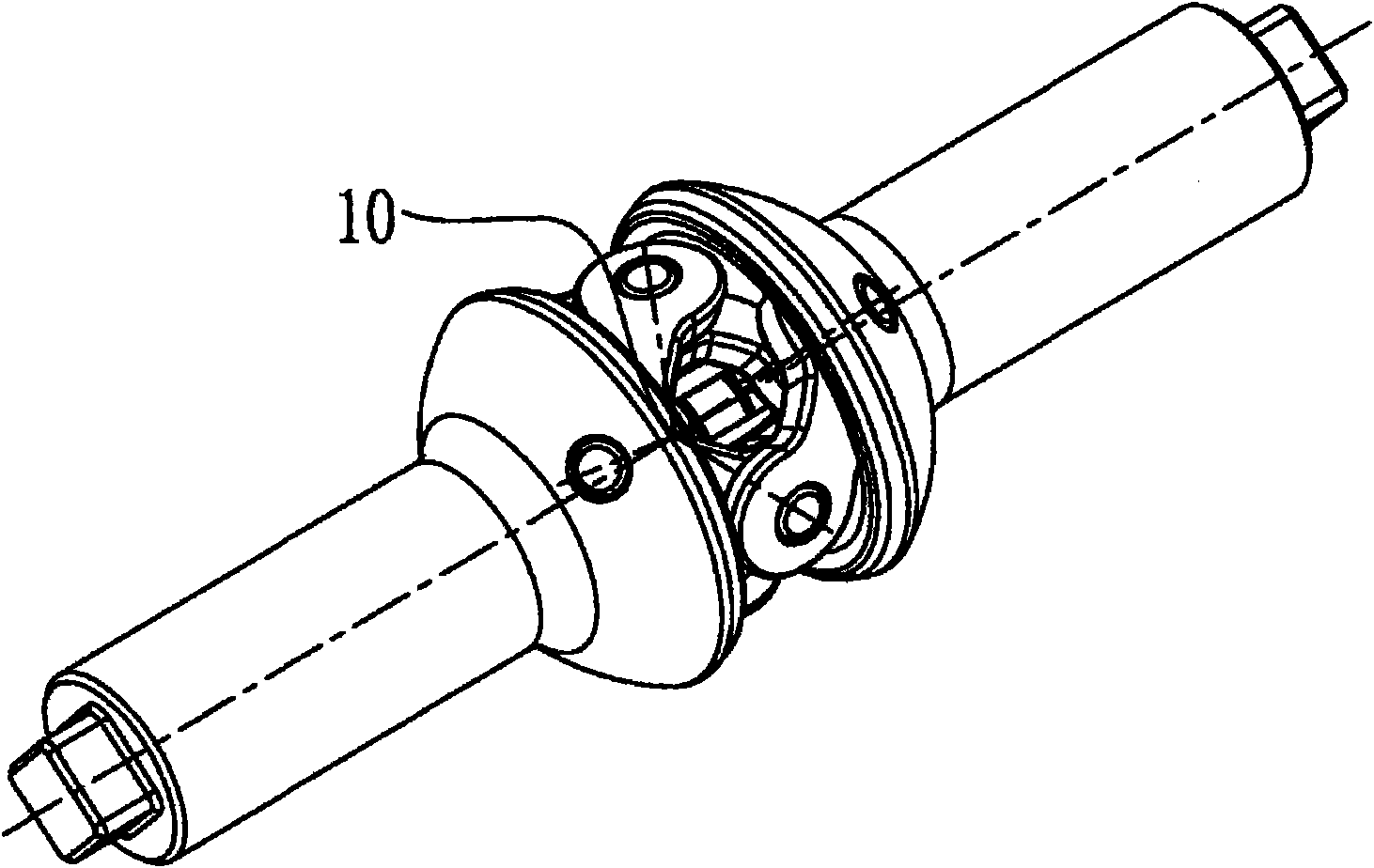
The invention relates to a constant-speed universal coupling comprising a driving shaft (21), a driven shaft (22), spherical motion mechanisms (25) and a bisecting mechanism (28), wherein the constant-speed transmission of the driving shaft (21) and the driven shaft (22) at any included angle within a permitted angle range can be realized; two groups or more than two groups of the spherical motion mechanisms (25) are distributed in the circumferential direction of a bisector (83) of a supplementary angle of an included angle between the driving shaft (21) and the driven shaft (22); the spherical motion mechanisms (25) are connected with the driving shaft (21) through pins (23) to form driving shaft rotary pairs, and the central axes of the driving shaft rotary pairs are axes (A23); the spherical motion mechanisms (25) are connected with the driven shaft (22) through pins (24) to form driven shaft rotary pairs, and the central axes of the driven shaft rotary pairs are axes (A24); the spherical motion mechanisms (25) are connected with the bisecting mechanism (28) to form middle rotary pairs, and the central axes of the middle rotary pairs are axes (A28); other spherical motion mechanisms are respectively connected with the driving shaft (21), the driven shaft (22) and the bisecting mechanism (28) in same ways, the central axes of all formed rotary pairs are intersected on a point (30), and the central axes of all the middle rotary pairs are in a symmetrical plane (82) positioned between the driving shaft (21) and the driven shaft (22).

Description

1 technical field [0001] The present invention relates to a coupling between shafts, especially a coupling capable of making the instantaneous rotational speeds of the driving and driven shafts at any angle within the allowable angle range the same, and in a specific form involves a constant velocity universal joint Axis device. 2 background technology [0002] Since the industrial age, people have been looking for a coupling that can keep the speed between the driving and driven shafts at any angle consistent at any time. [0003] The most common is the cross cardan coupling designed four hundred years ago. It can only realize the transmission of motion between the driving and driven shafts at any angle, but it cannot realize constant speed transmission. [0004] In order to achieve constant speed transmission, people later invented the double cross cardan coupling, which is composed of a driving shaft, an intermediate shaft and a driven shaft. By making the angle between ...

Claims


Application Information

Patent Timeline
Patent Type & Authority Applications(China)
IPC IPC(8): F16D3/30
Inventor 陈用毅
Owner 陈用毅
Learn More