Valve plate driving mechanism of sealing cavity

A technology for sealing the cavity and driving mechanism, which is applied in the direction of engine components, sliding valves, valve details, etc., can solve the problems of complex parts processing, operation and maintenance, complex structure of the worm gear valve plate driving device, and high equipment configuration costs, and achieve The effect of low equipment configuration cost, easy implementation and simple structure

Inactive Publication Date: 2012-02-29
DONGGUAN ANWELL DIGITAL MASCH CO LTD
View PDF0 Cites 1 Cited by
  • Summary
  • Abstract
  • Description
  • Claims
  • Application Information

AI Technical Summary

Problems solved by technology

[0005] However, the structure of the worm gear valve plate driving device is relatively complicated, and the processing, operation and maintenance of parts are relatively complicated, which is difficult to implement and the cost of equipment configuration is relatively high.

Method used


Image

  • Valve plate driving mechanism of sealing cavity
  • Valve plate driving mechanism of sealing cavity
  • Valve plate driving mechanism of sealing cavity

Examples


Embodiment Construction

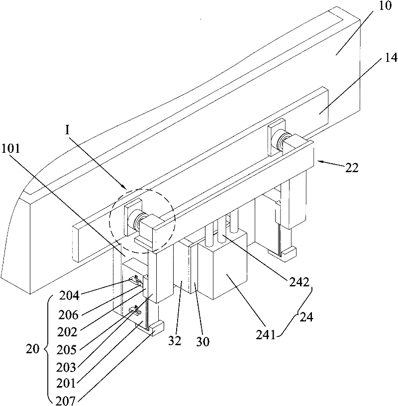
[0024] Embodiments of the present invention will now be described with reference to the drawings, in which like reference numerals represent like elements. As mentioned above, the present invention provides a valve plate driving mechanism for a sealed cavity. Since the first driving device of the valve plate driving mechanism for a sealed cavity of the present invention drives the valve plate to perform longitudinal linear reciprocating motion through the mounting plate, The second driving device drives the valve plate to perform horizontal linear reciprocating motion, thereby realizing the process of the valve plate opening or closing the transmission window of the sealed cavity. The structure is simple and compact, and the movement is flexible and light. The processing, operation and maintenance are relatively simple, easy to implement, and the equipment configuration cost is low.

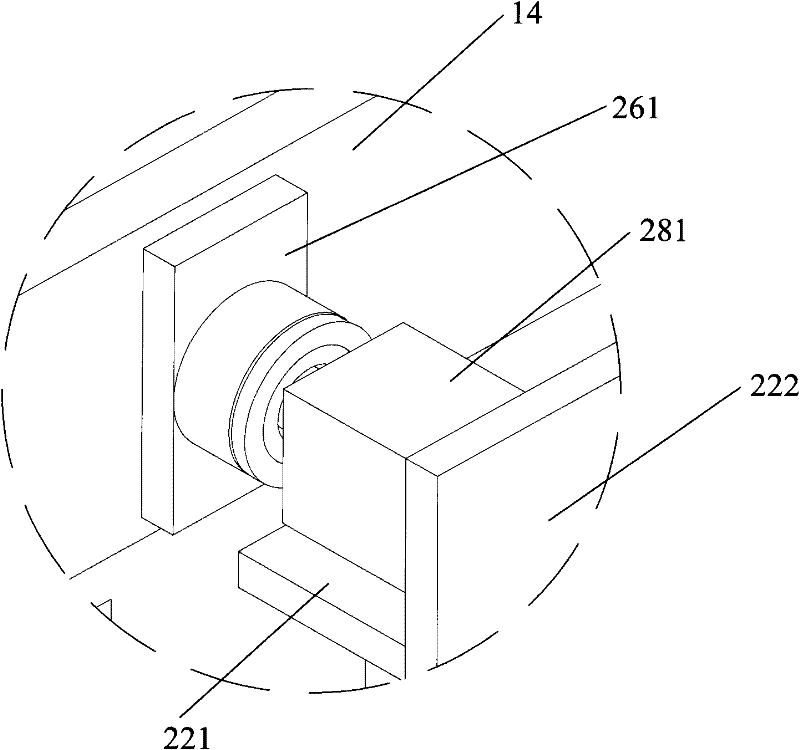
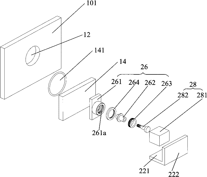
[0025] Please refer to Figure 1-3 , the sealing cavity valve plate driving mechanism of the...


PUM


Abstract

The invention discloses a valve plate driving mechanism of a sealing cavity, comprising a movable guiding device, a mounting plate, a first driving device, a connecting device and a second driving device. The movable guiding device is arranged below a transferring window of the sealing cavity and fixedly connected with the outer side wall of the sealing cavity, the mounting plate is longitudinally and glidingly connected with the movable guiding device and fixedly connected with the first driving device, and the connecting device is respectively connected with a valve plate and the second driving device which is respectively connected with the connecting device and the mounting plate. The valve plate driven by the first driving device of the valve plate driving mechanism of the sealing cavity through the mounting plate to make longitudinal linear reciprocating motion and driven by the second driving device to make transversal linear reciprocating motion so as to realize the process ofopening or closing the transferring window through the valve plate and have the advantages of simple and compact structure, flexible and convenient action, very simple processing and operation of spare parts, easy implementation and lower equipment configuration cost.

Description

technical field [0001] The invention relates to a sealed cavity used for providing a vacuum environment in the field of vacuum coating, and more particularly relates to a valve plate driving mechanism for opening or closing a transfer window of the sealed cavity. Background technique [0002] In the organic light emitting diode (English: Organic Light Emitting Diode, referred to as: OLED) industry and the solar panel industry, a large number of substrates need to be coated, and the sealed cavity (also called, vacuum chamber) required for coating body) is essential. In order to facilitate the input of the substrate to be coated into the sealed cavity from the outside or the output of the coated substrate from the sealed cavity, a transfer window for the substrate to enter and exit is usually set on the sealed cavity, and through the The valve plate is used to realize the opening or closing of the above-mentioned transfer window. [0003] In the prior art, a worm gear valve ...

Claims


Application Information

Patent Timeline
Patent Type & Authority Patents(China)
IPC IPC(8): F16K31/122
CPCF16K3/188F16K51/02
Inventor 杨明生郭远伦刘惠森范继良王勇王曼媛
Owner DONGGUAN ANWELL DIGITAL MASCH CO LTD
Why Eureka
Try Eureka