Cavity antennas for electronic device

A technology of electronic equipment and resonant cavity, which is applied in the direction of resonant antenna, antenna, slot antenna, etc., and can solve the problems of realizing antenna and so on.

Active Publication Date: 2011-01-26
APPLE INC
View PDF5 Cites 69 Cited by
  • Summary
  • Abstract
  • Description
  • Claims
  • Application Information

AI Technical Summary

Problems solved by technology

This makes it difficult to implement antennas in electronic devices that contain conduc

Method used


Image

  • Cavity antennas for electronic device
  • Cavity antennas for electronic device
  • Cavity antennas for electronic device

Examples


Embodiment Construction

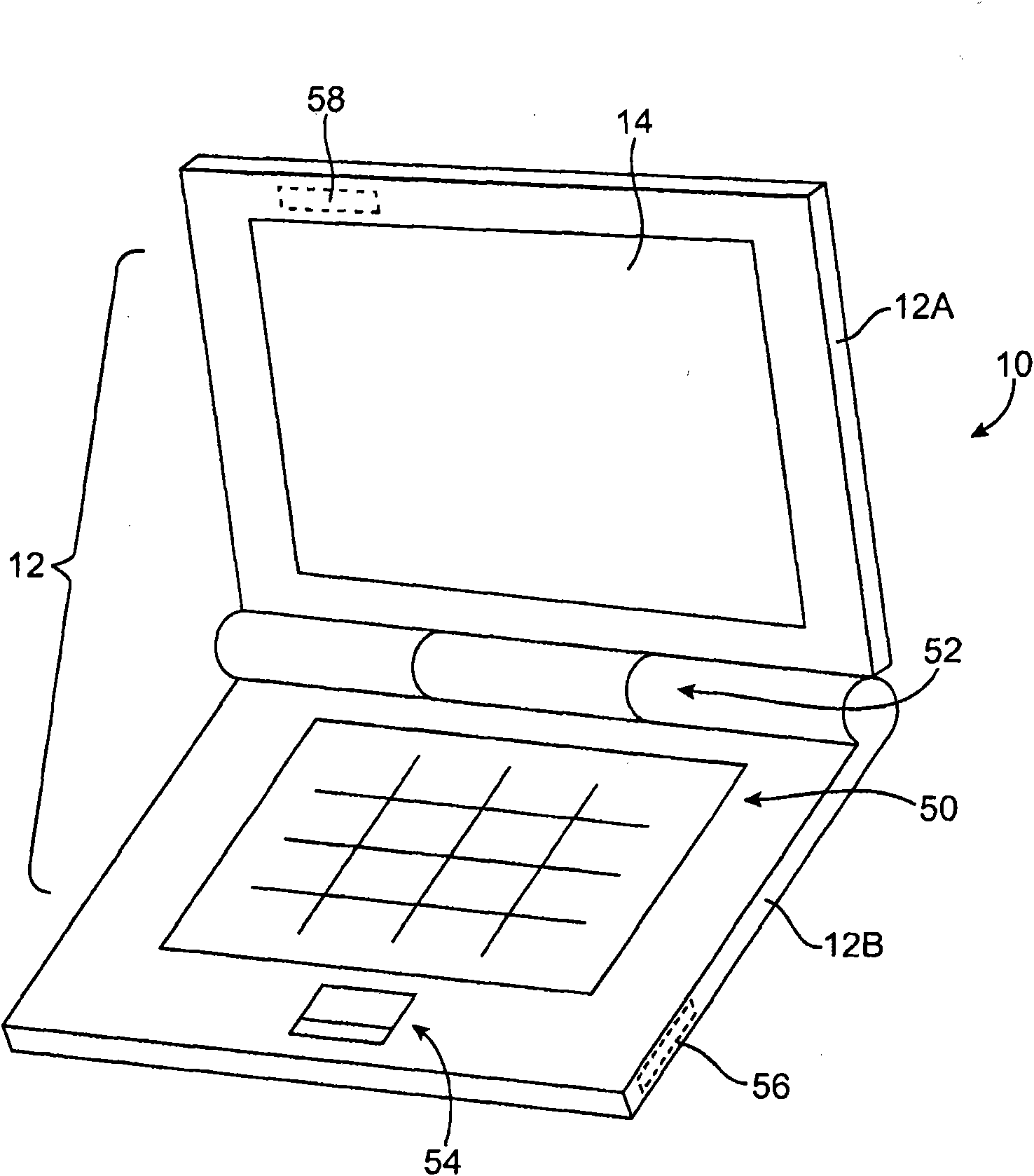
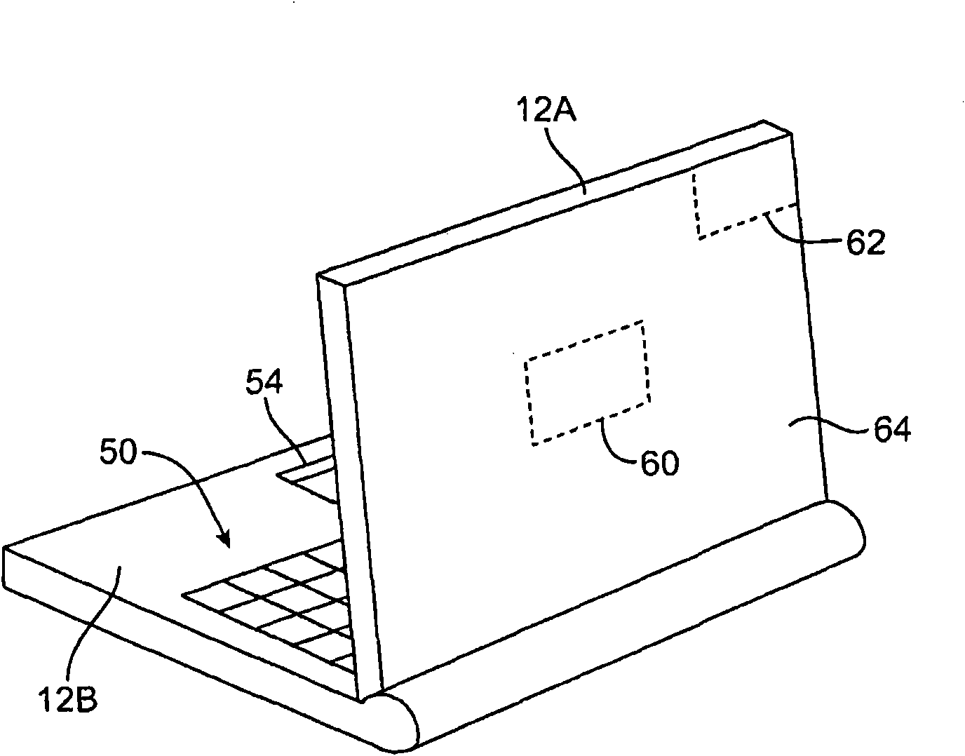
[0033] Electronic devices may have wireless communication circuitry. Wireless communication circuitry may be used to support wireless communication in one or more wireless communication frequency bands. Antenna structures in electronic devices are used to transmit and receive radio frequency signals. For example, single-band and multi-band antennas can be formed. Each antenna may have an antenna resonating element. The antenna resonating element may be based on an inverted-F design, a slot configuration, or other antenna resonating element arrangements. The antenna may have an antenna resonator. Antenna resonators can help isolate antennas in electronic devices from nearby electronic components and can help improve antenna efficiency. The antenna can be installed behind the antenna window. The antenna window may be formed by a slot in the conductive structure.

[0034] Any suitable electronic device may have an antenna. As examples, antennas may be formed in electronic ...


PUM


Abstract

Antennas are provided for electronic devices such as portable computers. An electronic device may have a housing in which an antenna is mounted. The housing may have an antenna window for the antenna. The antenna window may be formed from dielectric or from antenna window slots in a conductive member such as a conductive wall of the electronic device housing. An antenna may have an antenna resonating element that is backed by a conductive antenna cavity. The antenna resonating element may have antenna resonating element slots or may be formed using other antenna configurations such as inverted-F configurations. The antenna cavity may have conductive vertical sidewalls and a conductive rear wall. The antenna cavity walls may be formed from conductive layers on a dielectric antenna support structure.

Description

[0001] This application claims priority to US Patent Application Serial No. 12 / 500,570, filed July 9, 2009, which is hereby incorporated by reference in its entirety. technical field [0002] This application relates generally to antennas, and more particularly to antennas for electronic devices. Background technique [0003] Electronic devices, such as portable computers and handheld electronic devices, are becoming more and more popular. Devices such as these often have wireless communication capabilities. For example, an electronic device may use long-range wireless communication circuitry (eg, cellular telephone circuitry) to communicate using the 850 MHz, 900 MHz, 1800 MHz, and 1900 MHz cellular telephone bands (eg, the primary Global System for Mobile Communications or GSM cellular telephone bands). Long-range wireless communication circuits can also be used to handle the 2100MHz band and other frequency bands. Electronic devices may use short-range wireless communic...

Claims


Application Information

Patent Timeline
IPC IPC(8): H01Q1/24H01Q1/38H01Q5/01H01Q9/04H01Q13/10H01Q5/10
CPCG06F1/1616H01Q13/18H01Q1/38H01Q1/2266G06F1/1698G06F1/1626H01Q1/2258H01Q5/20
Inventor B·基昂D·B·基奥E·A·瓦兹奎兹G·A·斯普里格胥浩R·W·斯科卢巴E·L·卡马乔M·帕斯科林尼J·古特曼蒋奕R·A·G·安古鲁R·卡巴勒罗
Owner APPLE INC
Why Eureka
Try Eureka