
Method, device and system for realizing time synchronization

A time synchronization and time technology, applied in the field of communication, can solve problems such as delay jitter, unpredictable data volume, transmission delay jitter, etc., and achieve the effect of high-precision time synchronization

Inactive Publication Date: 2011-01-26
HUAWEI TECH CO LTD
View PDF0 Cites 28 Cited by
  • Summary
  • Abstract
  • Description
  • Claims
  • Application Information

AI Technical Summary

Problems solved by technology

[0007] In the process of carrying IEEE1588 frames through microwaves, the inventors found at least the following problems in the prior art: in the process of carrying IEEE1588 frames in microwaves, it is first necessary to encapsulate / adapt IEEE1588 frames. The / adaptation process usually adds an Idle frame with a fixed length of 5 bytes to achieve rate adaptation, and the addition of the Idle frame will cause the position of the IEEE1588 frame in the microwave frame to change, resulting in the IEEE1588 frame in the microwave channel. The transmission of the transmission will produce delay jitter, and because the Idle frame is randomly inserted, the amount of data in the Idle frame is unpredictable, so the transmission delay jitter is unpredictable, so that the IEEE1588 frame is transmitted over the microwave channel The Delay required for the transmission is different, even if the transmission delay between the synchronization time between the master and slave devices is different
Therefore, according to the performance of the clock synchronization protocol, it is obtained: T2=T1+Delay1+Offset; T4=T3+Delay2-Offset; there are 3 unknown parameters in the above two equations, namely: Delay1, Delay2 and Offset, so it is impossible to obtain from the above two equations In this equation, calculate the time difference Offset of the slave device's own clock relative to the master device's own clock. In the prior art, the difference in Delay is ignored. Assuming that the Delay between the master and slave devices is the same, the Offset is calculated, so that it can only be used in a certain Roughly realize the clock synchronization between the wireless base station and the network controller within the error range

Method used


Image

  • Method, device and system for realizing time synchronization
  • Method, device and system for realizing time synchronization
  • Method, device and system for realizing time synchronization

Examples


Embodiment 1

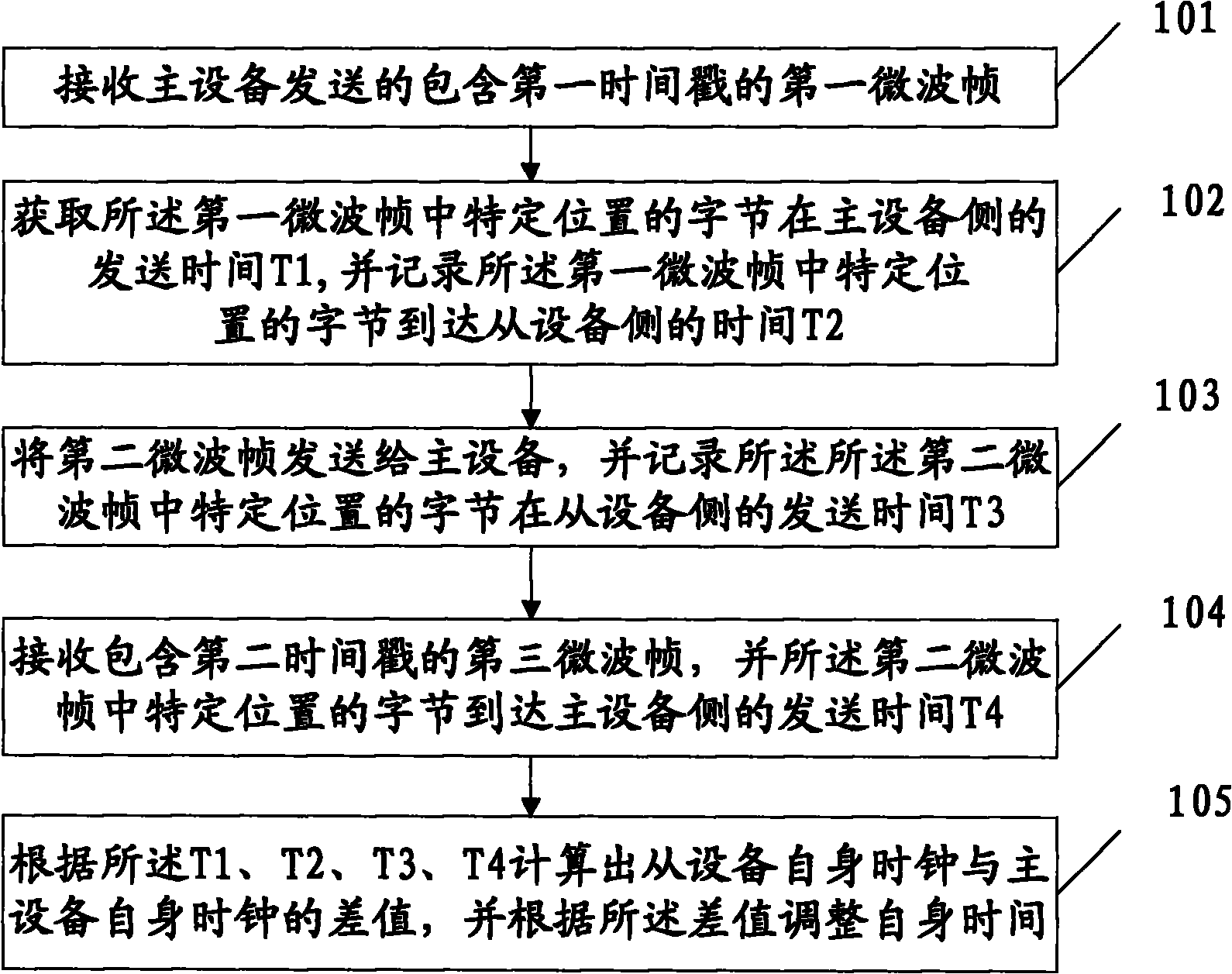
[0046] An embodiment of the present invention provides a method for realizing time synchronization, such as figure 1 As shown, the method includes:

[0047] 101. Receive a first microwave frame including a first time stamp sent by a master device; wherein, the first time stamp is the sending time T1 of a byte at a specific position in the first microwave frame on the master device side; Wherein, the specific position may be, but not limited to, the following form: a specific position in the header of the microwave frame, for example, the position of the last byte of the header of the microwave frame.

[0048] 102. Acquire the first timestamp in the first microwave frame, and record the time T2 when the byte at a specific position in the first microwave frame arrives at the slave device side; since the first timestamp is encapsulated in the microwave frame , after the slave device receives the first microwave frame, it needs to parse the first microwave frame to obtain the fir...

Embodiment 2

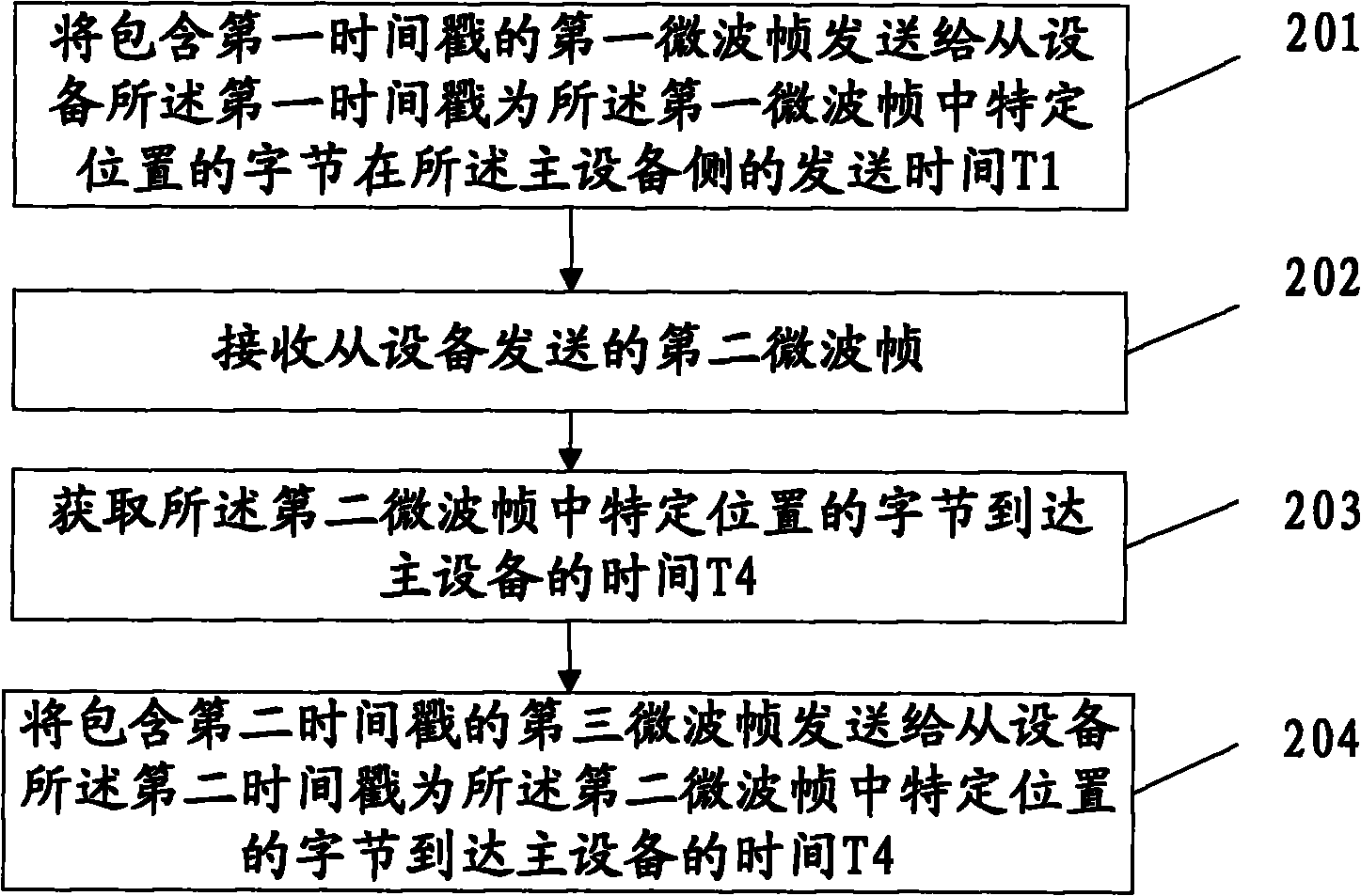
[0070] An embodiment of the present invention provides a method for realizing time synchronization, such as Figure 6 As shown, the method includes:

[0071] 601. Send a first microwave frame including a first timestamp to a slave device, where the first timestamp is the sending time T1 of a byte at a specific position in the first microwave frame on the master device side.

[0072] Wherein, before sending the first microwave frame containing the first time stamp to the slave device, the master device first synchronizes its own clock to an absolute time source according to the existing technology, and calculates the time of a specific position in the first microwave frame The sending time T1 of the byte on the master device side; after the sending time T1 is calculated, the first timestamp is carried in the payload of the clock synchronization protocol, and the clock synchronization protocol frame can be but not limited to IEEE1588 frame, the present invention takes the clock s...


PUM


Abstract

The invention discloses a method, a device and a system for realizing time synchronization and relates to the field of communication for realizing high-precision time synchronization between a wireless base station and a network controller. The invention comprises the following steps of: receiving a first microwave frame including the sending time T1 of bytes in specific positions in the first microwave frame at a master unit side and acquiring the sending time T1; recording a time T2 on arriving at a slave unit by the bytes in the specific positions in the first microwave frame; sending a second microwave frame to the master unit and recording the sending time T3 of bytes in specific positions in the second microwave frame at the slave unit side; receiving a third microwave frame including a second time stamp which is used as a time T4 on arriving at the master unit by the bytes in the specific positions in the second microwave and acquiring the time T4; and calculating the time difference between a slave unit self clock and a master unit self clock according to T1, T2, T3 and T4, and adjusting self time according to the time difference. The embodiment of the invention is mainly applied to the process of microwave transmission.

Description

technical field [0001] The present invention relates to the technical field of communication, in particular to a method, device and system for realizing time synchronization. Background technique [0002] Microwave transmission does not need to lay optical fibers or cables but directly transmits data through space, so it has obvious engineering advantages in cities or remote and special areas (such as mountainous areas). Due to the flexible and convenient networking and usage of microwave transmission, microwave systems are gradually widely used in wireless base station backhaul transmission applications. [0003] In the evolution process of wireless base stations from 2G, 2.5G / 2.75G, 3G to 4G, in addition to the increase in microwave capacity requirements, transmission of high-quality synchronization time is also an important feature that microwave needs to support, so as to realize wireless base station and RNC (Radio Network Controller, wireless network controller) to ac...

Claims


Application Information

Patent Timeline
IPC IPC(8): H04B7/26H04W56/00H04W84/20
CPCH04J3/0667
Inventor 李昆高思龙龙昊
Owner HUAWEI TECH CO LTD
Learn More