Supercharge Your Innovation With Domain-Expert AI Agents!

Electric tool

A technology of electric tools and tool heads, which is applied in the direction of manufacturing tools, metal processing equipment, portable drilling rigs, etc., can solve the problems of complex structure and high cost of the gearbox, and achieve the effect of simplifying the rear gearbox and reducing the number of stages

Inactive Publication Date: 2011-02-02
JOHNSON ELECTRIC SHENZHEN
View PDF7 Cites 2 Cited by
  • Summary
  • Abstract
  • Description
  • Claims
  • Application Information

AI Technical Summary

Problems solved by technology

However, in the existing multi-stage gear reduction method, the structure of the gearbox is complicated and the cost is high

Method used


Image

  • Electric tool
  • Electric tool
  • Electric tool

Examples


Embodiment Construction

[0020] The technical solutions and other beneficial effects of the present invention will be apparent through the detailed description of specific embodiments of the present invention below in conjunction with the accompanying drawings.

[0021] The following will combine Figure 1 to Figure 3 Embodiments of the present invention will be described. Understandably, the electric tool of the present invention may be an electric drill, electric hammer, electric saw, electric planer, electric wrench and the like. To simplify the description, an electric drill is taken as an example below.

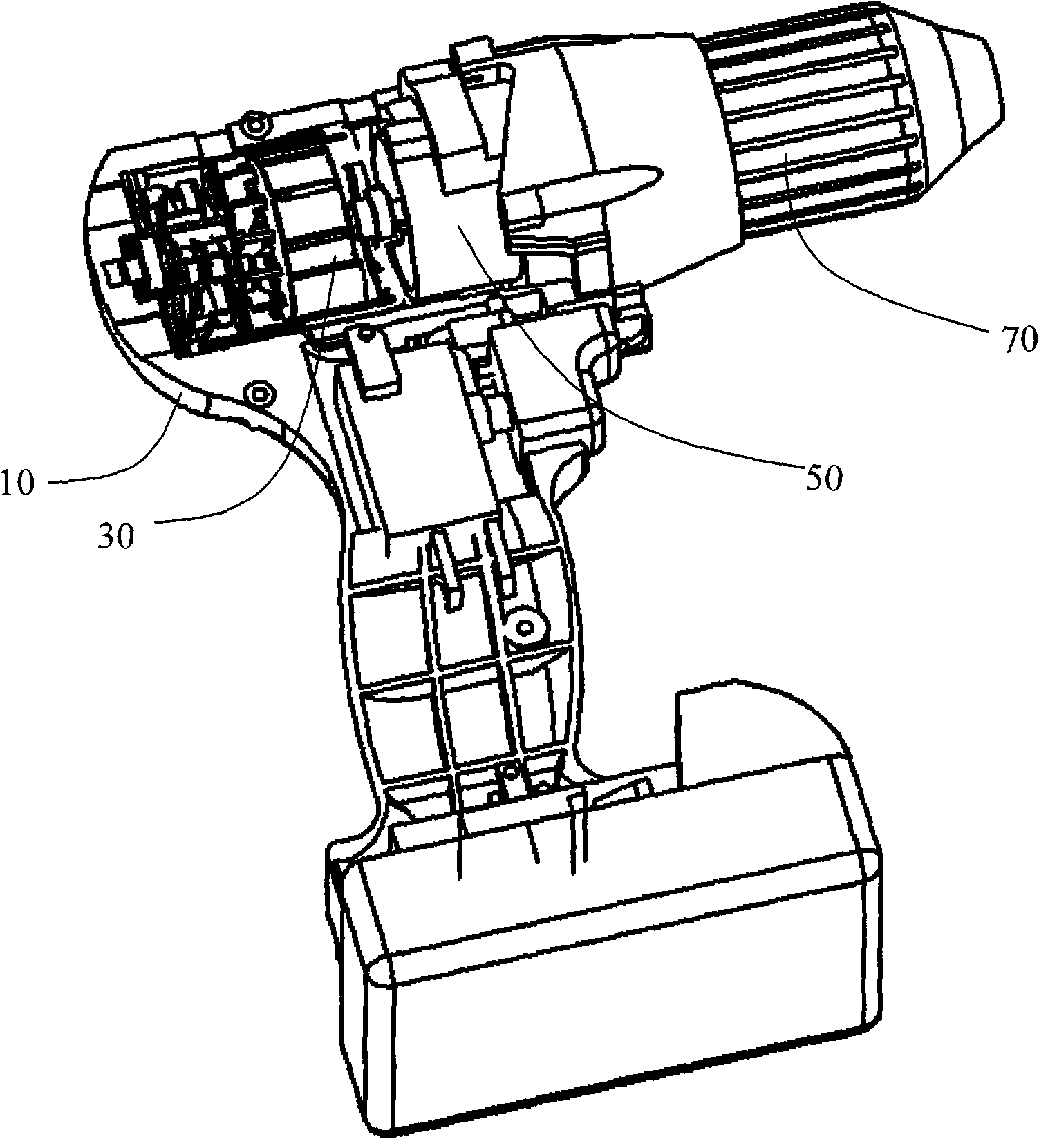
[0022] see figure 1 , the electric drill includes a housing 10, a motor 30 installed in the housing 10, a reduction mechanism 50 connected to the output shaft 32 of the motor, and a drill bit 70 driven by the reduction mechanism.

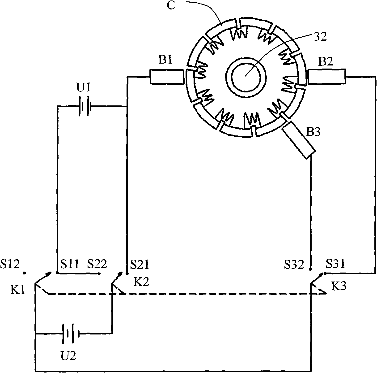
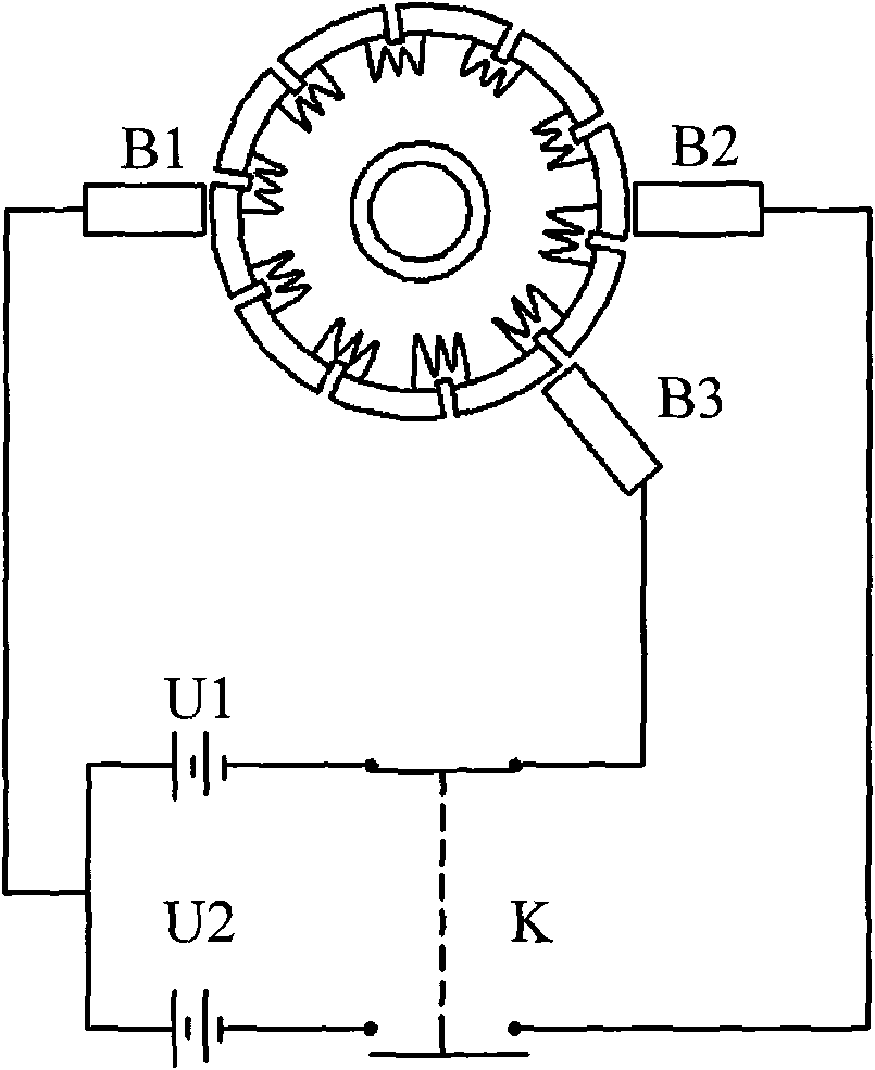
[0023] see figure 2 , the motor 30 is a DC motor, including a commutator C installed on the motor output shaft 32, a shared carbon brush B1, a low-speed carbon b...


PUM


Abstract

The invention provides an electric tool, comprising a casing, a direct current motor arranged in the casing, a speed-reducing mechanism connected with an output shaft of the motor and a tool head driven by the speed-reducing mechanism, wherein the motor comprises a commutator arranged on the output shaft, a shared carbon brush, a high-speed carbon brush, a low-speed carbon brush, at least one direct current power supply and a switch device connected with the carbon brushes and the power supply; when the switch device is connected with the power supply, the shared carbon brush and the high-speed carbon brush, the output shaft of the motor operates at high speed, so that the tool head works at higher speed; and when the switch device is connected with the power supply, the shared carbon brush and the low-speed carbon brush, the output shaft of the motor operates at low speed, so that the tool head works at lower speed. By utilizing the switch device to select different carbon brushes and corresponding power supply combinations or resistance settings, different output speeds of the motor can be obtained, the stage number of a rear connected gearbox can be reduced and thereby the rear connected gearbox can be simplified.

Description

technical field [0001] The invention relates to an electric tool. Background technique [0002] In general electric tools, the motor output shaft is usually connected to multi-stage gear reduction, so that the motor can be applied to different speed occasions. For example, when the electric drill is drilling, the electric drill bit is required to have a high output speed, and when the electric drill is screwing, the drill bit is required to have a relatively low output speed. However, in the existing multi-stage gear reduction method, the structure of the gear box is complicated and the cost is high. [0003] Therefore, the present invention aims to provide an electric tool that can improve the above problems. Contents of the invention [0004] The present invention also provides an electric tool comprising: a housing, a motor installed in the housing, a deceleration mechanism connected to the output shaft of the motor, and a tool head driven by the deceleration mechanis...

Claims


Application Information

Patent Timeline
IPC IPC(8): B23B45/02
Inventor 刘清式
Owner JOHNSON ELECTRIC SHENZHEN
Features
  • R&D
  • Intellectual Property
  • Life Sciences
  • Materials
  • Tech Scout
  • Unparalleled Data Quality
  • Higher Quality Content
  • 60% Fewer Hallucinations
Learn More