Gas power nail gun

A gas-powered, nail-shooting technology, applied in nailing tools, manufacturing tools, etc., can solve problems such as difficulty in ensuring the balance of force on the left and right striker arms, skewed combustion cylinder, deformation under force, etc., and achieves a simple structure , smooth movement, balanced force effect

Active Publication Date: 2011-02-02
NANJING TENGYA PRECISE TECH DEV CO LTD
View PDF11 Cites 4 Cited by
  • Summary
  • Abstract
  • Description
  • Claims
  • Application Information

AI Technical Summary

Problems solved by technology

However, it was found during use that the separation structure is difficult to ensure the balance of force on the left and right striker arms, causing the combustion cylinder to be skewed, causing poor movement, or causing deformation or damage to the joints of the left and right striker arms, resulting in functional failure

Method used


Image

  • Gas power nail gun
  • Gas power nail gun
  • Gas power nail gun

Examples


Embodiment 1

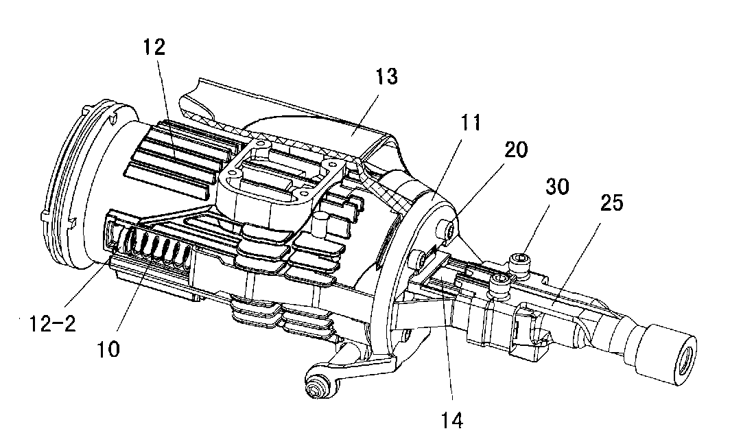
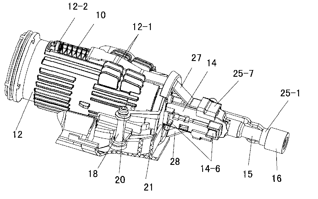
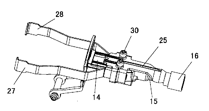
[0066] The gas power nail gun of the present embodiment is as Figure 1 to Figure 4Shown, its casing 13 inside is equipped with cylinder block 12, and this cylinder block 12 bottoms are nailing seat 14. The nailing seat 14 is fastened to the cylinder block 12 by screws 20 . The nailing seat 14 bottom is provided with the striking head 25 that is fixedly connected with the left and right striking arms 27 and 28 by screws 30 . The two sides of the cylinder block 12 are respectively formed with a guide groove 12-1 formed by heat dissipation ribs and an overhanging flange 12-2. The left and right striker arms 27 and 28 are respectively embedded in the guide grooves 12-1 on both sides, and the upper top surfaces 27-7 and 28-7 of the left and right striker arms are respectively connected with the outwardly extending The flanges 12-2 engage. Both sides of the nailing seat 14 are shaped on vertical slide rails 14-1, and the lower end is equipped with a gun nozzle 15, and a conduit ...


PUM


Abstract

The invention relates to a gas power nail gun, belonging to the technical field of gas power tools. The lower part of a cylinder body in a casing of the nail gun is fixedly connected with a nailing seat; a bunting head is installed at the lower part of the nailing seat; an extending flange and guide grooves are respectively arranged at two sides of the cylinder body; a left bunting arm and a right bunting arm are respectively embedded in the guide grooves at two sides; the upper end surfaces of the bunting arms are connected with the extending flange through a bunting arm spring; vertical slide rails are arranged at two sides of the nailing seat; a gun nozzle and a guide tube are installed at the lower end; a guard board inner wall and a guard board which are vertical to positioning planes are respectively extended on the positioning planes of two sides of the upper end of the bunting head; the guard board inner wall and the guard board are connected by inner wall steps; the guard board inner wall and the nailing seat form a moving pair; the lower ends of the left bunting arm and the right bunting arm are respectively provided with inner walls; and the lower end surfaces of the inner walls are abutted on the corresponding inner wall steps. The invention has simple structure, material saving and economic cost, and the parts are mutually tenoned and embedded into a whole after assembling, thus ensuring that the left bunting arm and the right bunting arm are under balanced stress.

Description

technical field [0001] The invention relates to a nail gun, in particular to a gas powered nail gun, which belongs to the technical field of gas power tools. Background technique [0002] A nail gun is a tool that drives a nail into an object by power. The gas nail gun ignites the mixture of air and fuel to generate power to drive the nails into the workpiece and the hard substrate to realize the connection between the workpiece and the hard substrate, greatly improving work efficiency, mobility and convenience. [0003] At present, the patent documents related to nail guns have application number 200410098396.4, titled "Nail Gun", application number 200510048800.1, title "Nail Gun with Safety Protection Device", application number 200710067672.4, title "With The Chinese patent application of "Nail Shooting Gun with Anti-Airborne Hitting Function"; see also the patent documents of US Patent No. US5197647, US5195646, US7182237. [0004] The search found that U.S. Patent No....

Claims


Application Information

Patent Timeline
Patent Type & Authority Applications(China)
IPC IPC(8): B25C1/08
Inventor 蔡德宝刘春龙
Owner NANJING TENGYA PRECISE TECH DEV CO LTD
Why Eureka
Try Eureka