
Variable optical attenuator capable of compensating WDL by adjusting optical waveguide position

A technology of attenuator and optical waveguide, which is applied in the coupling of optical waveguide, optics, instruments, etc., can solve the problem of not considering position adjustment, etc., and achieve the effect of increasing dispersion

Inactive Publication Date: 2011-02-02
BEIJING WAVELINK TECH
View PDF5 Cites 10 Cited by
  • Summary
  • Abstract
  • Description
  • Claims
  • Application Information

AI Technical Summary

Problems solved by technology

The position adjustment is not considered here to change the dispersion to compensate the effect of MFD on WDL

Method used


Image

  • Variable optical attenuator capable of compensating WDL by adjusting optical waveguide position
  • Variable optical attenuator capable of compensating WDL by adjusting optical waveguide position
  • Variable optical attenuator capable of compensating WDL by adjusting optical waveguide position

Examples


Embodiment Construction

[0046] The specific implementation manners of the present invention will be further described in detail below in conjunction with the accompanying drawings. It should be noted that the embodiment of the adjustable optical attenuator that compensates the wavelength-dependent loss by adjusting the position of the optical waveguide according to the present invention is only an example, but the present invention is not limited to this specific embodiment.

[0047] Hereinafter, a specific example of the technical concept of VOA compensating WDL in the present invention will be described in detail.

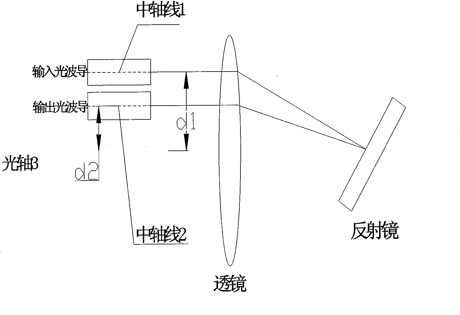
[0048] Such as Figure 2a As shown, the VOA according to the present invention includes: an adjustable input optical fiber, a lens with an optical axis 3, a tiltable mirror, and an adjustable output optical fiber with a core and a coating. Figure 2b The VOA with waveguide position adjustment according to the present invention is shown in the attenuation state, where the angle of the mir...


PUM


Abstract

The invention relates to a variable optical attenuator based on a reflecting mirror, in particular to a wavelength dependent loss (WDL) compensation variable optical attenuator capable of compensating the wavelength dependent loss by adjusting the optical waveguide position. In a reflecting variable optical attenuator (VOA) system, through adjusting the position of the input optical waveguide on an input surface and the position of the output optical waveguide on an output surface, the transmission path of the light beam containing different wavelength components in a lens, chromatic dispersion generated by the lens self is increased, and the wavelength dependent loss (WDL) is compensated.

Description

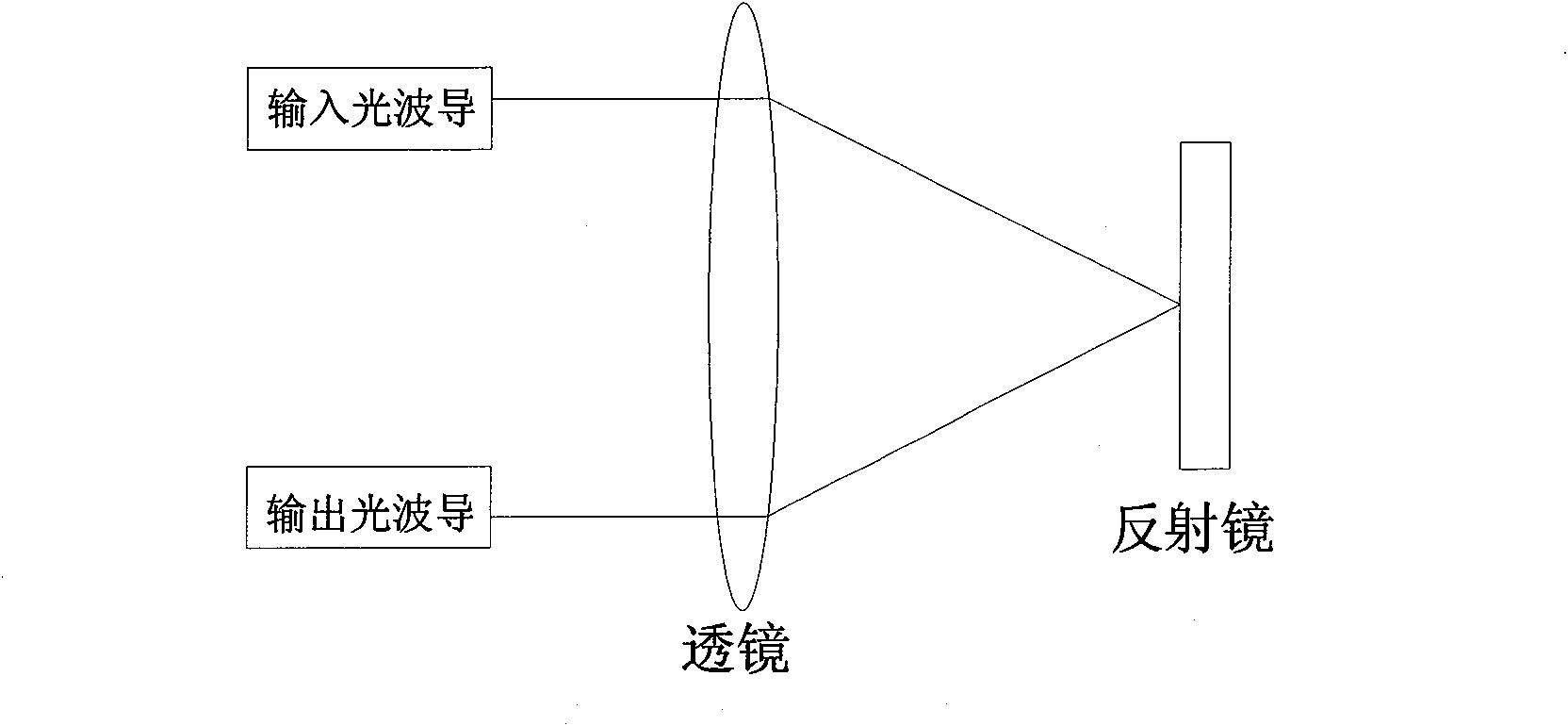
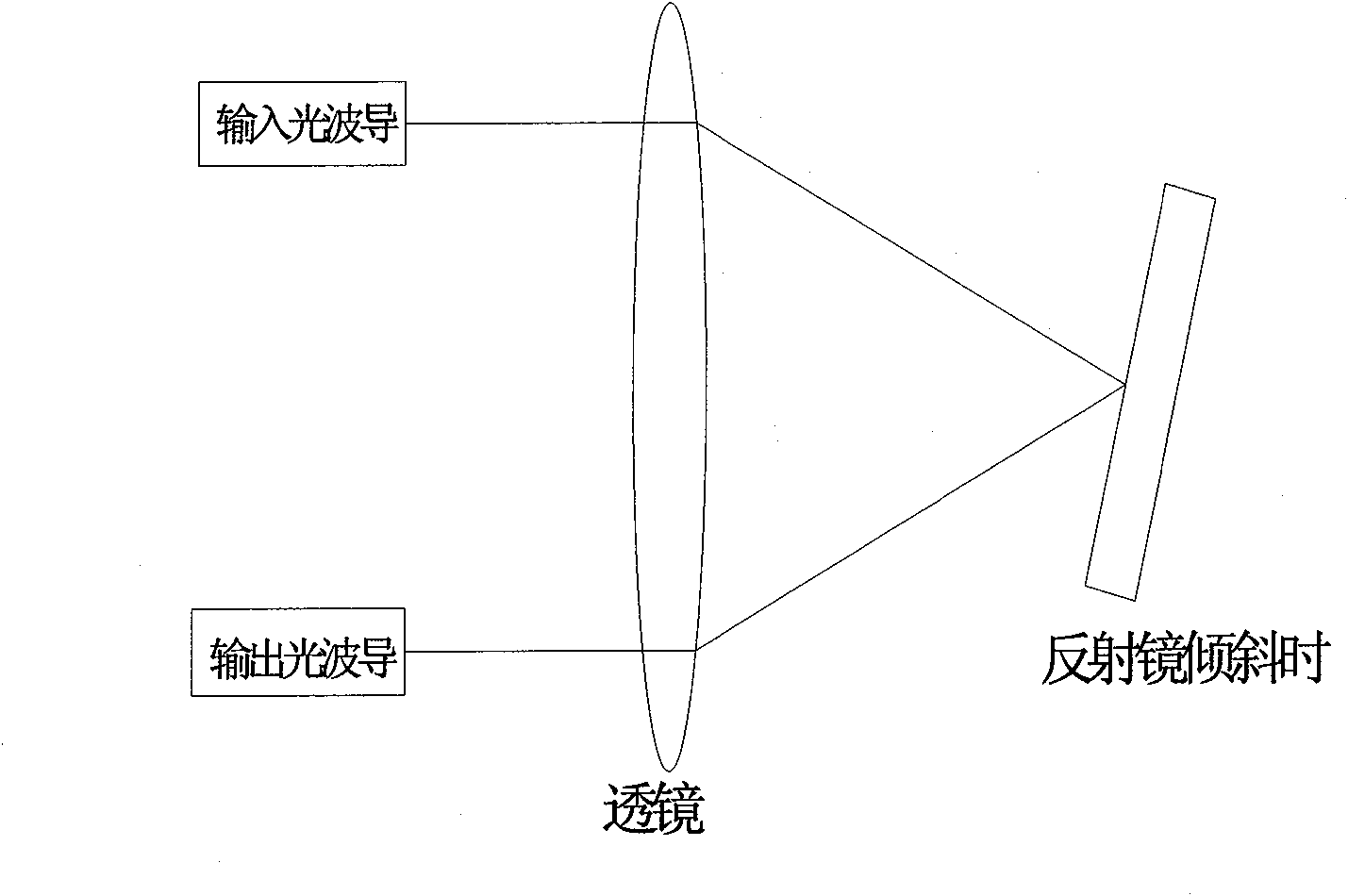
technical field [0001] The present invention relates to a mirror-based adjustable optical attenuator (Variable Optical Attenuator, VOA) system, in particular to a wavelength-dependent loss compensation variable optical attenuator, which adopts changing the position of the input optical waveguide and the output optical waveguide, increasing the system Dispersion, thereby compensating for wavelength dependent loss (WDL). Background technique [0002] Figure 1a , 1b shows the general reflective VOA basic structure. Figure 1a is the case when IL is the smallest in the prior art, and Figure 1b It is the situation in the attenuation state in the prior art. Such as Figure 1a As shown, a common reflective VOA includes: a lens, a mirror, an input optical waveguide, and an output optical waveguide. The beams containing different wavelength components derived from the output light wave are collimated by the lens, and then reflected by the mirror to form a reflected beam. The ref...

Claims


Application Information

Patent Timeline
Patent Type & Authority Applications(China)
IPC IPC(8): G02B26/08G02B6/26
Inventor 涂化丁必锋
Owner BEIJING WAVELINK TECH
Learn More