Power supply circuit and control method thereof

A technology of power supply circuit and control method, which is applied in the direction of electric lamp circuit layout, energy-saving control technology, electric light source, etc., can solve problems such as audio noise, instability, and damage to electronic components of known power supply circuits, and achieve the goal of not being easily damaged and reducing audio noise Effect

Inactive Publication Date: 2011-02-02
DELTA ELECTRONICS INC
View PDF3 Cites 1 Cited by
  • Summary
  • Abstract
  • Description
  • Claims
  • Application Information

AI Technical Summary

Problems solved by technology

[0007] The main purpose of the present invention is to provide a power supply circuit and its control method, which solves the problem that the input current of the known power supply circuit is turned on or off at the same time due to multiple switch circuits being turned on or off at the same time in the known power supply circuit. The sharp rise or fall will generate audio noise. In addition, when multiple switch circuits are turned on at the same time in the known power supply circuit, a huge surge current will be generated due to the sharp rise of the input current, which makes the known power supply circuit easy to crash and become unstable. And cause damage to the electronic components in the known power supply circuit

Method used


Image

  • Power supply circuit and control method thereof
  • Power supply circuit and control method thereof
  • Power supply circuit and control method thereof

Examples


Embodiment Construction

[0061] Some typical embodiments embodying the features and advantages of the present invention will be described in detail in the description in the following paragraphs. It should be understood that the present invention can be changed in various ways without departing from the scope of the present invention, and that the description and illustrations therein are illustrative in nature rather than limiting the present invention.

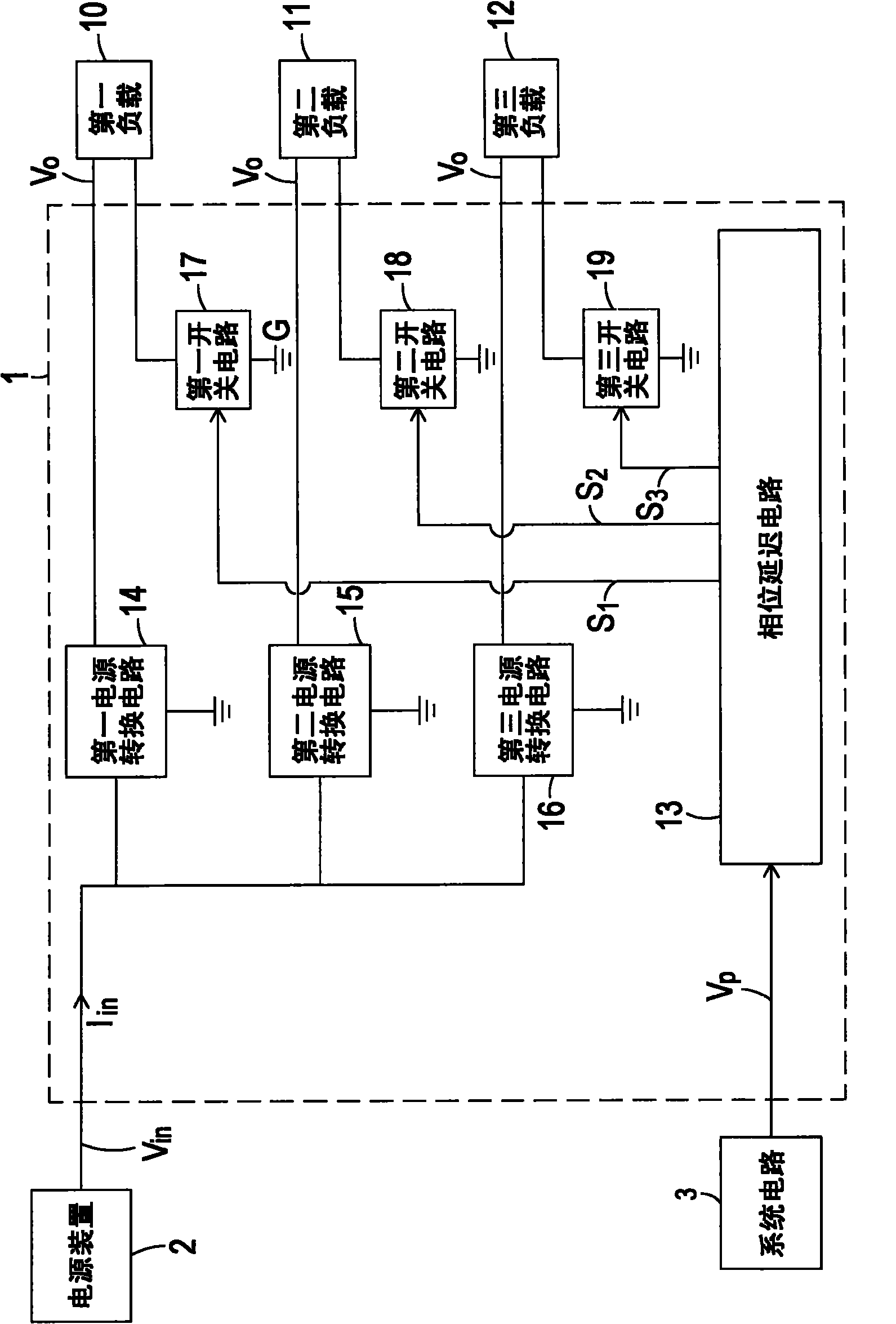
[0062] see figure 1 , which is a circuit block diagram of a power supply circuit in a preferred embodiment of the present invention. Such as figure 1 As shown, the power supply circuit 1 of this embodiment is connected to a power supply device 2 and multiple loads, such as figure 1 The first load 10, the second load 11 and the third load 12 shown, the power supply circuit 1 receives an input voltage V through the power supply device 2 in , and this input voltage V in conversion while outputting multiple drive voltages V o To the first load 10 ,...


PUM


Abstract

The invention relates to a power supply circuit and a control method thereof. The power supply circuit receives input voltages to drive a plurality of loads, and comprises a plurality of switch circuits, a plurality of power conversion circuits and a phase deviation circuit; the plurality of switch circuits are respectively connected with the plurality of loads, the plurality of power conversion circuits are respectively connected with the plurality of switch circuits and the plurality of loads for converting the input voltages so as to provide a plurality of driving voltages to the plurality of loads when the corresponding switch circuits are conducted, and the phase deviation circuit is connected with the plurality of switch circuits and a system circuit for generating a plurality of delay signals to the control ends of the plurality of switch circuits according to the switch signals of the system circuit so as to ensure that the plurality of switch circuits are conducted or cut off, wherein the plurality of delay signals are converted to an enable state from a disable state at different time so as to ensure that the plurality of switch circuits are conducted at different time. According to the invention, the input currents do not rise or fall sharply when the plurality of switch circuits carry out action, therefore, the generation of audio noise is reduced, the stability is better, and the electronic elements are not easy to be damaged.

Description

technical field [0001] The invention relates to a power supply circuit and a control method thereof, in particular to a power supply circuit with a plurality of switch circuits and a control method thereof. Background technique [0002] In recent years, with the advancement of technology, various loads that need to be driven by electricity and have different functions have been gradually developed, such as light-emitting diodes. These loads with various functions not only satisfy people with different needs, but also integrate into everyone's daily life, making people's life more convenient. [0003] Generally speaking, all kinds of loads that need to be driven by electricity are connected to a power supply circuit, so as to start operation by providing appropriate electric energy through the power supply circuit. Taking the load as a light emitting diode as an example, when the light emitting diode is applied to a device such as a liquid crystal television, the light emitt...

Claims


Application Information

Patent Timeline
Patent Type & Authority Applications(China)
IPC IPC(8): H05B37/02H05B37/00
CPCY02B20/42Y02B20/40
Inventor 张世贤柯柏年
Owner DELTA ELECTRONICS INC
Why Eureka
Try Eureka