

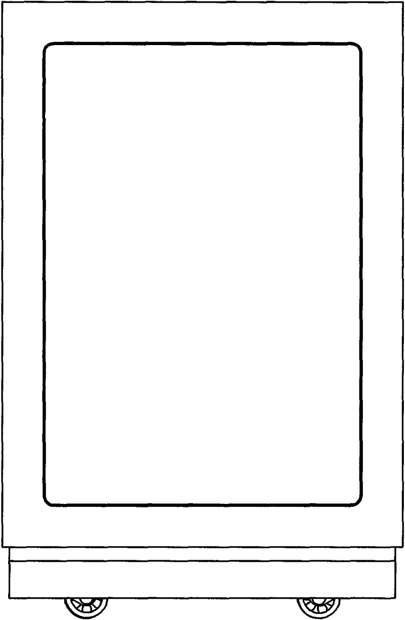
Rack foot of safety box
A technology for safes and legs, applied in safes, buildings, building structures, etc., to achieve the effect of easy manufacture and use, reasonable and practical structure, and avoiding the entry of sundries
- Summary
- Abstract
- Description
- Claims
- Application Information
AI Technical Summary
Problems solved by technology
Method used
Image

Examples
Embodiment 1
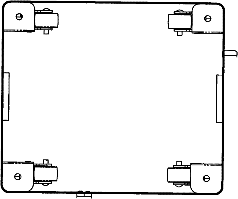
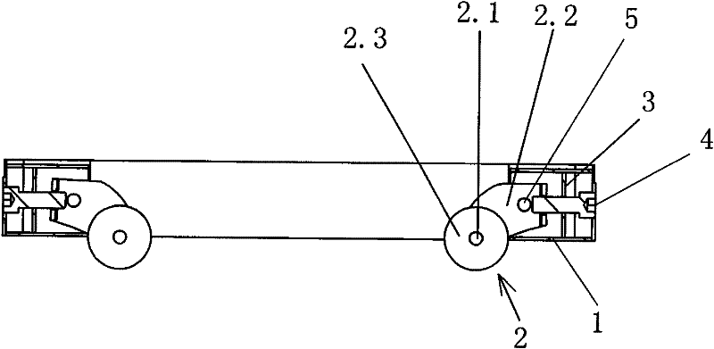
[0033] Example 1 as Figure 4 As shown, the frame foot of the safe cabinet is mainly composed of the frame foot panel 6 and the bracket fixing seat 1, the caster assembly 2, the bracket fixing plate 3, the bracket positioning pin 5, and the fastening screw 4; the frame foot panel 6 is connected by welding. At the bottom of the safe cabinet, a cavity 9 is formed for the caster assembly to be hidden. The frame foot panel 6 is welded and fixed with bracket fixing seats 1 at four corners, and the bracket fixing plate 3 is also welded and fixed in the bracket fixing seats 1; The caster assembly 2 is composed of a caster 2.3, a caster pin 2.1 and a caster bracket 2.2. The caster 2.3 is connected with the caster bracket 2.2 through the caster pin 2.1, and the caster bracket 2.2 is connected with the bracket fixing plate 3 and the bracket fixing seat through the bracket positioning pin 5 1, so that the caster assembly 2 is rotatably fixed on the bracket fixing seat 1 through the brack...
Embodiment 2
[0035] Example 2 as Figure 7-11 As shown, the foot of the safe cabinet is mainly composed of the foot wall 6 and the bracket fixing seat 1, the caster assembly 2, the bracket limit plate 3', the caster fixing pin 2.1, and the limit screw 4'; the frame foot wall 6 passes through The welding connection is arranged at the bottom of the safe cabinet, and the bracket fixing seat cavity 1a for the caster assembly 2 is formed through the bracket fixing seat 1 on the inner side, and the bracket fixing seat 1 is fixed on the frame foot panel 6 by welding The caster assembly 2 is composed of caster 2.3, caster pin 2.1 and caster bracket 2.2, the caster 2.3 is connected with the caster bracket 2.2 through the caster pin 2.1, and there is a bracket limiting plate between the bracket fixing seat 1 and the frame foot panel 6 3', the bracket limit plate 3' plays a limiting role on the caster fixing bracket 2.2, and also increases the load-bearing capacity of the stand; the caster fixing pin...
PUM
 Abstract
Description
Claims
Application Information