Automatic switching dual-voltage input power supply for massage armchair
A technology of automatic switching and input power supply, which is applied in the field of power supply and can solve problems such as unfavorable product promotion, differences, and increased costs
- Summary
- Abstract
- Description
- Claims
- Application Information
AI Technical Summary
Problems solved by technology
Method used
Image

Examples
Embodiment Construction
[0018] The embodiment of the present invention is used as the input power supply of the massage chair, and can provide three-way AC power supply to the main control board controlling the operation of the massage chair to meet the working requirements of the main control board of the massage chair.
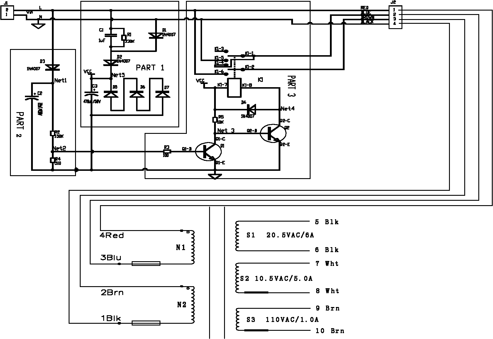
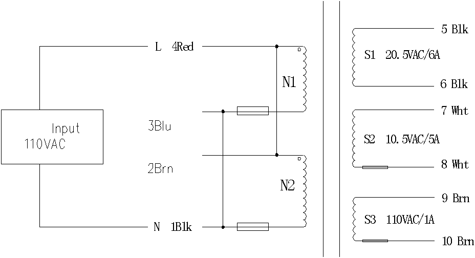
[0019] In order to make the main control board of the massage chair adapt to two different mains power sources (such as 110VAC and 220VAC), and at the same time keep the three-way AC power supply of the main control board stable and unchanged (such as 110VAC, 20.5VAC and 10.5VAC power supply ), it needs corresponding power supply to realize, and the present invention can meet the requirement. A detailed description will be given below in conjunction with the accompanying drawings.
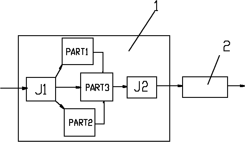
[0020] see figure 1 , the embodiment of the present invention is provided with a high-low voltage automatic switching module 1 and a dual-input transformer 2 . The input terminal of the high-low volta...
PUM
 Abstract
Description
Claims
Application Information
PatSnap Eureka turns technology decisions into work you can execute. Powered by our Innovation Knowledge Graph, it runs expert workflows across engineering, life sciences, materials and intellectual property. Get your review-ready output in minutes.


