Patient interface assembly for respiratory therapy

An interface component, patient technology, applied in respiratory masks, nebulizers for treatment, respirators, etc., can solve problems such as lowering

Active Publication Date: 2011-02-09
VYAIRE MEDICAL CONSUMABLES LLC
View PDF1 Cites 16 Cited by
  • Summary
  • Abstract
  • Description
  • Claims
  • Application Information

AI Technical Summary

Problems solved by technology

In general, HFO reduces saliva viscosity in vitro, which furt...

Method used


Image

  • Patient interface assembly for respiratory therapy
  • Patient interface assembly for respiratory therapy
  • Patient interface assembly for respiratory therapy

Examples


Embodiment Construction

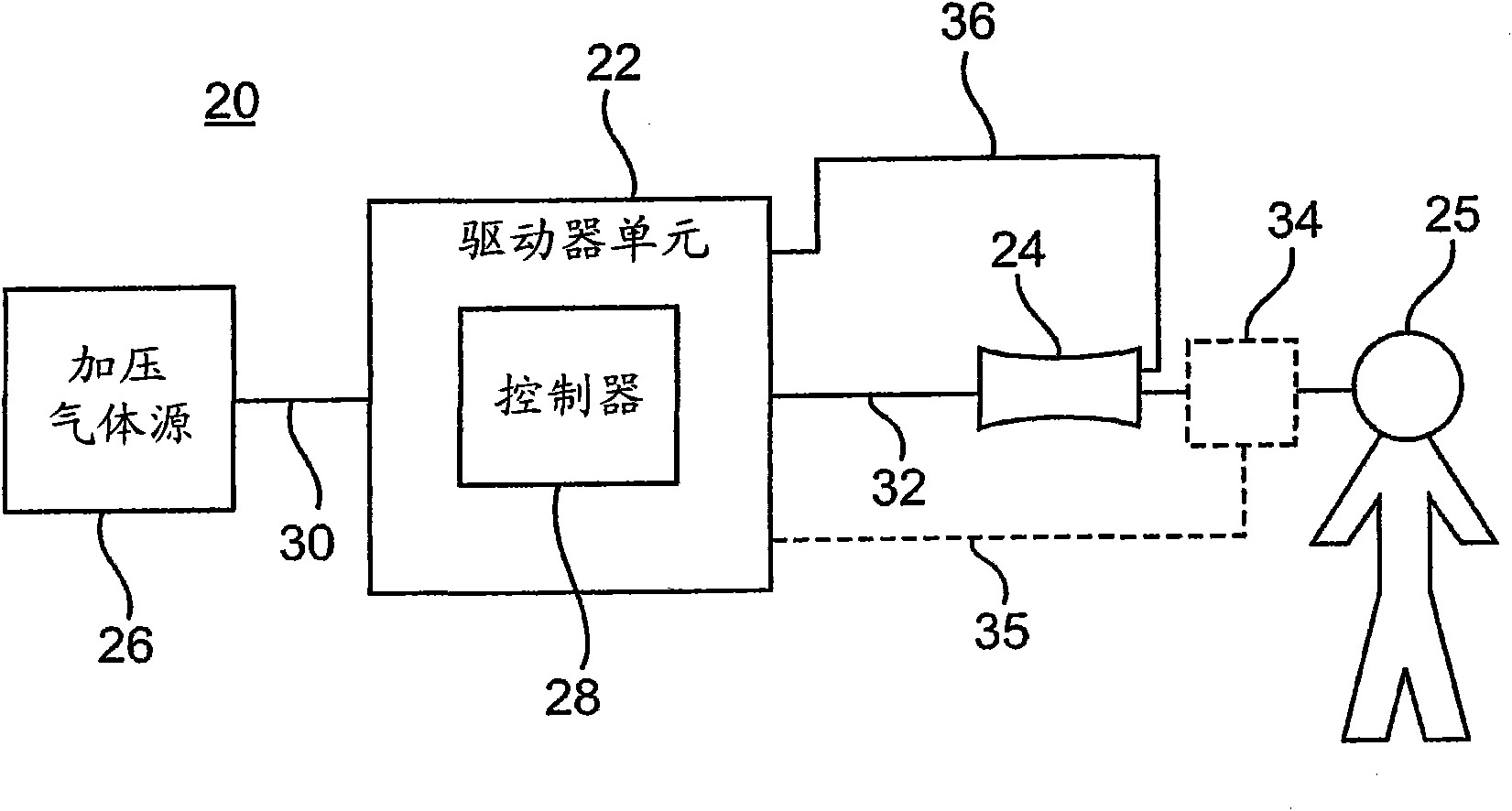
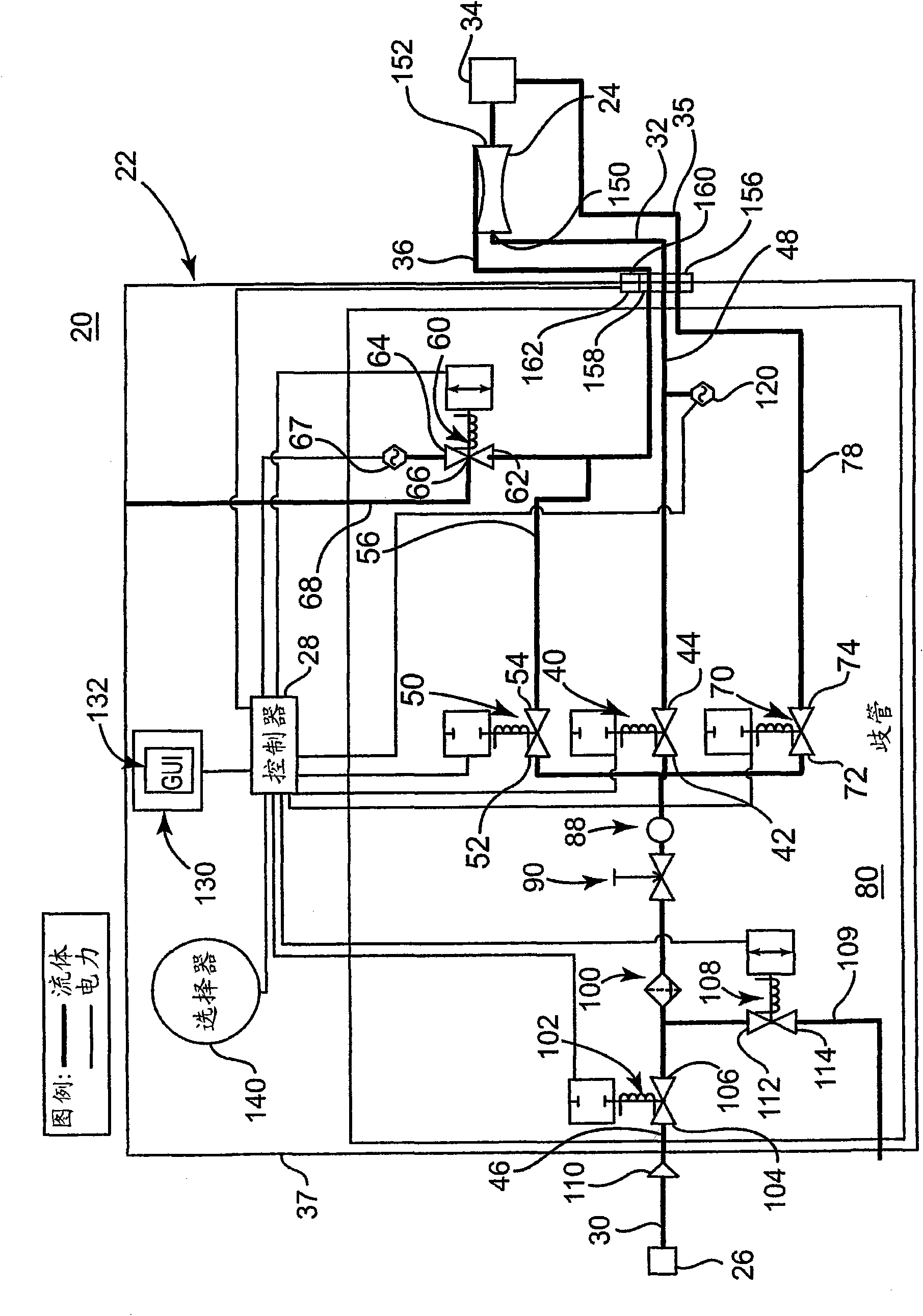
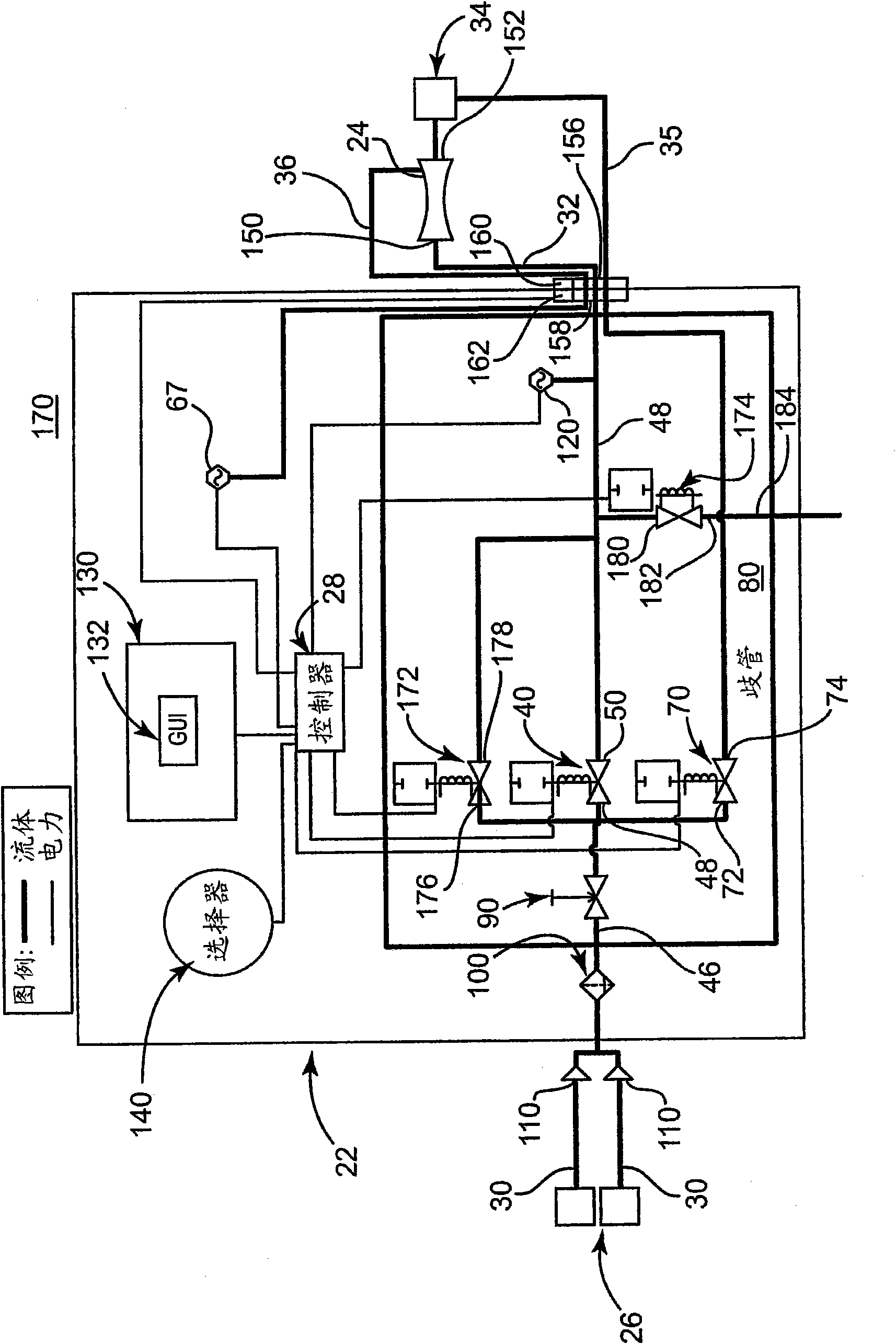
[0015] figure 1 is a schematic diagram of one embodiment of a respiratory therapy system 20 that includes a driver unit 22 and a patient interface device 24 that serves as a patient interface circuit that, in use, establishes connections to and from a patient 25. breathing tube. In particular, the breathing conduit extends to the airway (eg, mouth, sinuses, etc.) of the patient 25. In one embodiment, the breathing conduit to the airway of the patient 25 may be established by means of intubation. Furthermore, the system 20 can be used with or without a ventilator, if desired. Details of each component will be described below. In general, however, the driver unit is adapted to be fluidly connected to a source of pressurized gas (eg, an air source, an oxygen source, etc.) 26 (general reference numeral), and includes a controller 28 for controlling the fluidly connected Operation of one or more electronic valves disposed between the inlet line 30 and the outlet line 32 . More ...


PUM


Abstract

A patient interface assembly includes a housing that defines an inlet port and an outlet port. A jet pump receives pressurized gas flow from the inlet port and delivers the gas flow to the outlet port. A nebulizer is fluidly coupled to the outlet port and positioned to introduce medication into the gas flow and deliver medicated gas flow to a patient.

Description

[0001] Cross References to Related Applications [0002] This application is based upon and claims the benefit of U.S. Provisional Patent Application Serial No. 60 / 988,977, filed November 19, 2007, and relates to a patent application entitled "Having Electric Mechanically Actuated Respiratory Therapy System," US Patent Application No. 12 / 274,066, both of which are hereby incorporated by reference in their entirety. technical field [0003] The present disclosure relates to respiratory therapy systems and devices. In particular, the present invention relates to patient interface assemblies configured for coupling to a respiratory therapy system for delivery of medication. Background technique [0004] A variety of respiratory therapy devices are currently available to assist, treat or improve a patient's respiratory health. For example, positive airway pressure (PAP) has been shown to be beneficial in improving oxygenation, increasing lung capacity, and reducing venous retu...

Claims


Application Information

Patent Timeline
IPC IPC(8): A61M11/00
CPCA61M2202/0208A61M16/12A61M2205/332A61M2205/502A61M2230/63A61M2202/0468A61M2016/127A61M2016/0027A61M11/06A61M16/08A61M16/0816A61M16/0051A61M16/0096A61M2205/702A61M2205/6054A61M16/14A61M16/1055A61M2230/60A61M16/0006A61M16/0012A61M16/0093A61M16/0858A61M16/1065A61M16/127A61M16/024A61M2230/005A61M11/00A61M16/0057A61M16/06A61M16/105A61M2205/18A61M2205/3331A61M2205/75A61M16/0003A61M16/201
Inventor T·J·邓斯摩尔G·C·维斯T·C·威尔施克L·P·明焦内
Owner VYAIRE MEDICAL CONSUMABLES LLC
Why Eureka
Try Eureka