Device for melt spinning multi-component fibers

A multi-component fiber and melt-spinning technology, applied in fiber processing, textile and papermaking, spinneret assemblies, etc., can solve problems such as large melt flow, small throughput, and large manufacturing complexity, and achieve high manufacturing Effect of precision, simple manufacturing process

Inactive Publication Date: 2011-02-09
OERLIKON TEXTILE GMBH & CO KG
View PDF6 Cites 8 Cited by
  • Summary
  • Abstract
  • Description
  • Claims
  • Application Information

AI Technical Summary

Problems solved by technology

However, due to the high number of orifices per unit area, individual melt channels for each orifice within the distributor assembly do not allow for a large melt flow
The alternative design of the distribution groove with a correspondingly large groove depth leads to the production problems already mentioned above.
[0006] The devices for melt spinning known from the prior art are therefore based on a distributor assembly for distributing and feeding a plurality of melt components to the spinneret holes, wherein the plate arrangement within the distributor assembly can only A low melt throughput is achieved, or the distributor plate of the distributor assembly can only be implemented with considerable manufacturing complexity and thus with a loss of manufacturing tolerances
However, large manufacturing tolerances in the manufacture of the distribution plates necessarily lead to sealing problems within the distributor assembly in which the distribution plates are held sealed one above the other

Method used


Image

  • Device for melt spinning multi-component fibers
  • Device for melt spinning multi-component fibers
  • Device for melt spinning multi-component fibers

Examples


Embodiment Construction

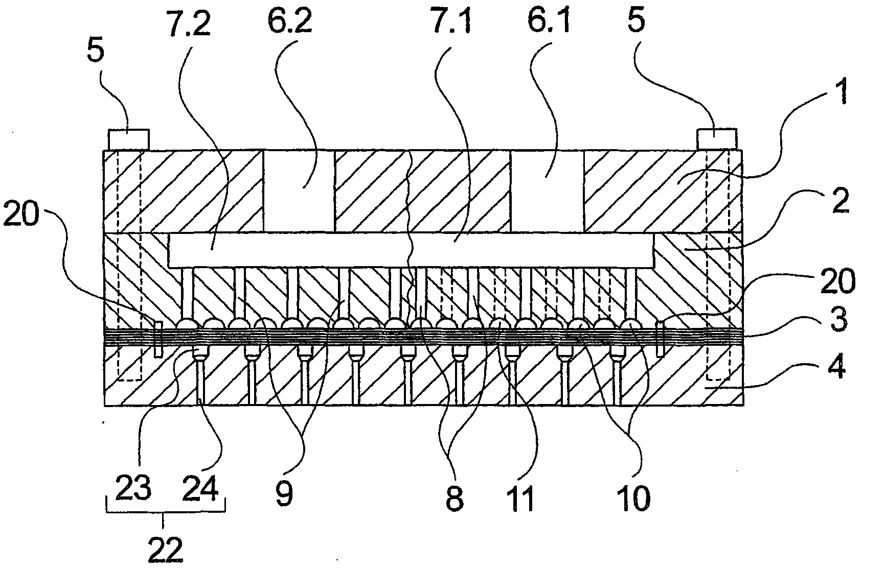
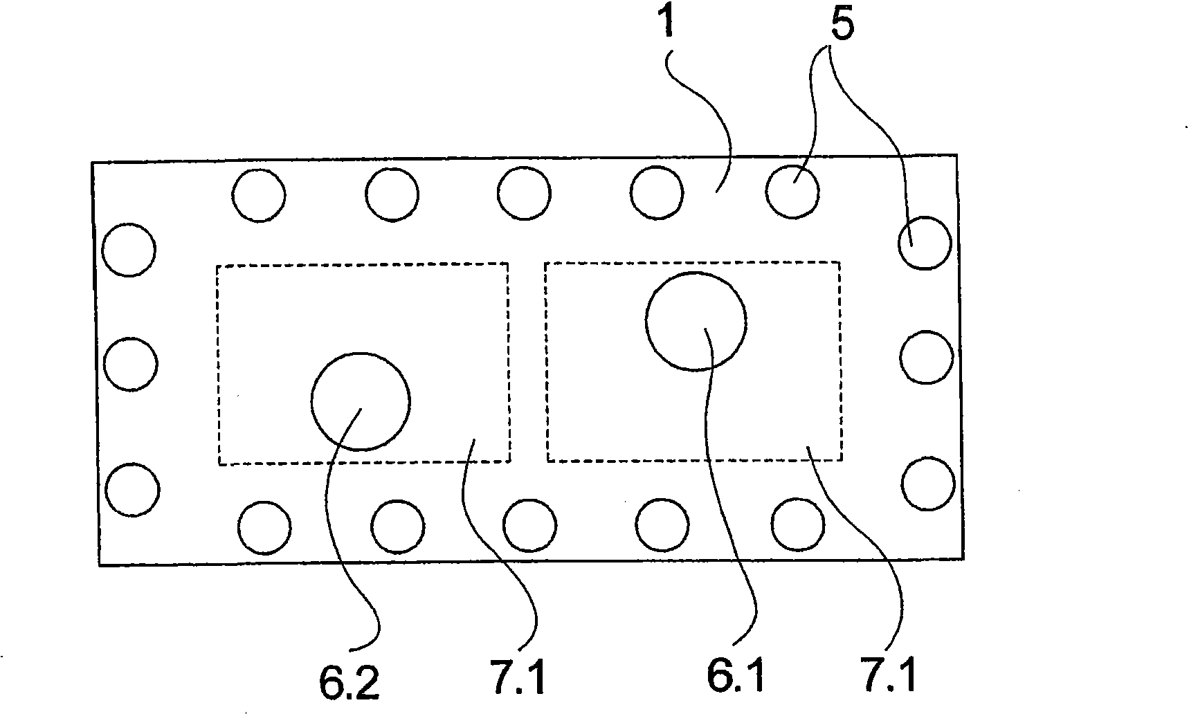
[0032] figure 1 and 2 Several views of the first embodiment are shown schematically. figure 1 is a cross-sectional view of the device, and figure 2 is a top view of the device. The following description applies to both figures, as long as it is not expressly indicated which figure is referred to.

[0033] according to figure 1 and 2The embodiment of has a plate structure formed by combining a plurality of rectangular plates. Therefore, an upper web 1 is provided which has two melt inlets 6.1 and 6.2. The melt inlets 6.1 and 6.2 are connected to two separate melt sources through melt pipes during operation, so that the two melt components can be independently fed to the device.

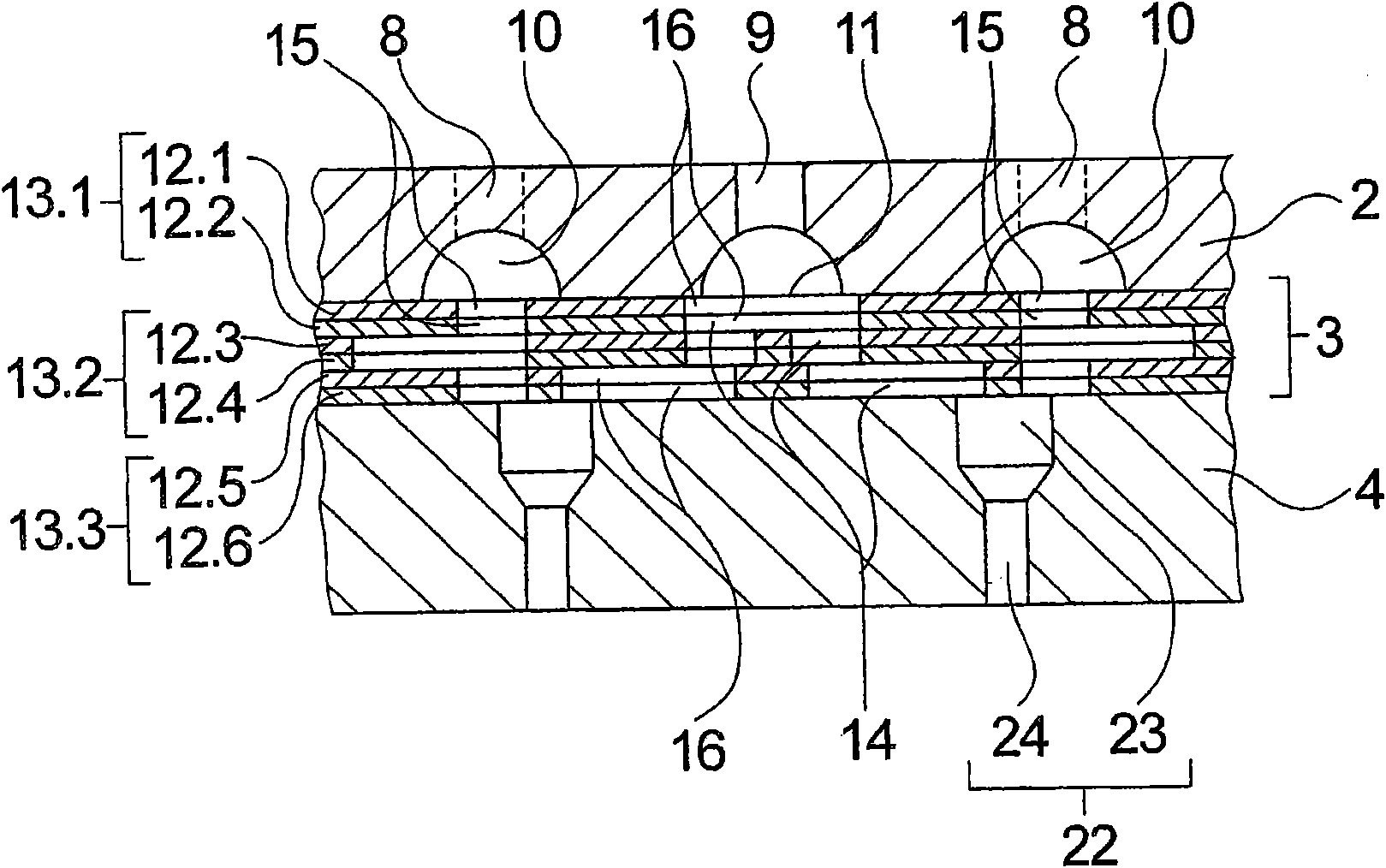
[0034] Feed plate 2 is connected to connecting plate 1 and has feed chambers 7.1 and 7.2 on the upper side for each melt inlet 6.1 and 6.2 respectively. Feed chambers 7.1 and 7.2 are connected to the underside of feed plate 2 via a plurality of melt channels. In this embodiment, the melt chan...


PUM


Abstract

The invention relates to a device for melt spinning multi-component fibers, comprising at least two melt inlets for introducing separately guided melt components. For this purpose, the device comprises a feed plate having a plurality of feed channels for distributing the melt components, a distributor block associated with the feed plate, and a nozzle plate adjoining the distributor block and comprising a plurality of nozzle bores, wherein the distributor block has several thin distributor plates that are stacked on top of each other and each have a hole pattern with multiple distribution openings. The thin distributor plates are configured inside the distributor block such that a plurality of melt channels form, which connect the feed channels of the feed plate to the nozzle bores of the nozzle plate. In order to implement high flow volumes, particularly for flows of the melt components on one plate plane of the distributor plates, multiple distributor plates having identical hole patterns of the distribution openings are stacked in a tightly sealing manner inside the distributor block. In this way, larger flow cross-sections can be implemented while adhering to simple manufacturing techniques for the production of such distributor plates.

Description

technical field [0001] The invention relates to a device for melt spinning multicomponent fibers according to the preamble of claim 1 . Background technique [0002] When melt spinning multicomponent fibers, the two melt components are extruded together through the orifice, so that the fiber strand produced through the orifice has multiple material components in cross-section. For example, bicomponent fibers can be produced from two incoming polymer materials, the cross-section of which has a sheath-core structure or a side-by-side structure. Such multicomponent fibers are usually extruded parallel to each other in large numbers, for example to produce filaments, tows or nonwovens. Here, the melt components must be distributed and fed separately to each spinneret orifice. In order to obtain a uniform distribution of the melt components over a large number of spinneret holes, it is preferred in the prior art to use devices for melt spinning multicomponent fibers in which th...

Claims


Application Information

Patent Timeline
Patent Type & Authority Applications(China)
IPC IPC(8): D01D5/34D01D5/32D01D4/06D01D5/30B29C48/345
CPCD01D5/30D01D4/06
Inventor M·格罗奈尔-罗特尔梅尔V·比克霍尔茨
Owner OERLIKON TEXTILE GMBH & CO KG
Why Eureka
Try Eureka