Coil selection for parallel magnetic resonance imaging

一种磁共振成像、物理线圈的技术,应用在磁场的大小/方向、测量磁变量、磁梯度测量等方向,能够解决存储器存储问题重建时间等问题,达到减少存储器和重建的负载的效果

Active Publication Date: 2011-02-09
KONINK PHILIPS ELECTRONICS NV
View PDF3 Cites 17 Cited by
  • Summary
  • Abstract
  • Description
  • Claims
  • Application Information

AI Technical Summary

Problems solved by technology

Using a large number of coil array elements can lead to memory storage issues and increased rebuild times

Method used


Image

  • Coil selection for parallel magnetic resonance imaging
  • Coil selection for parallel magnetic resonance imaging
  • Coil selection for parallel magnetic resonance imaging

Examples


Embodiment Construction

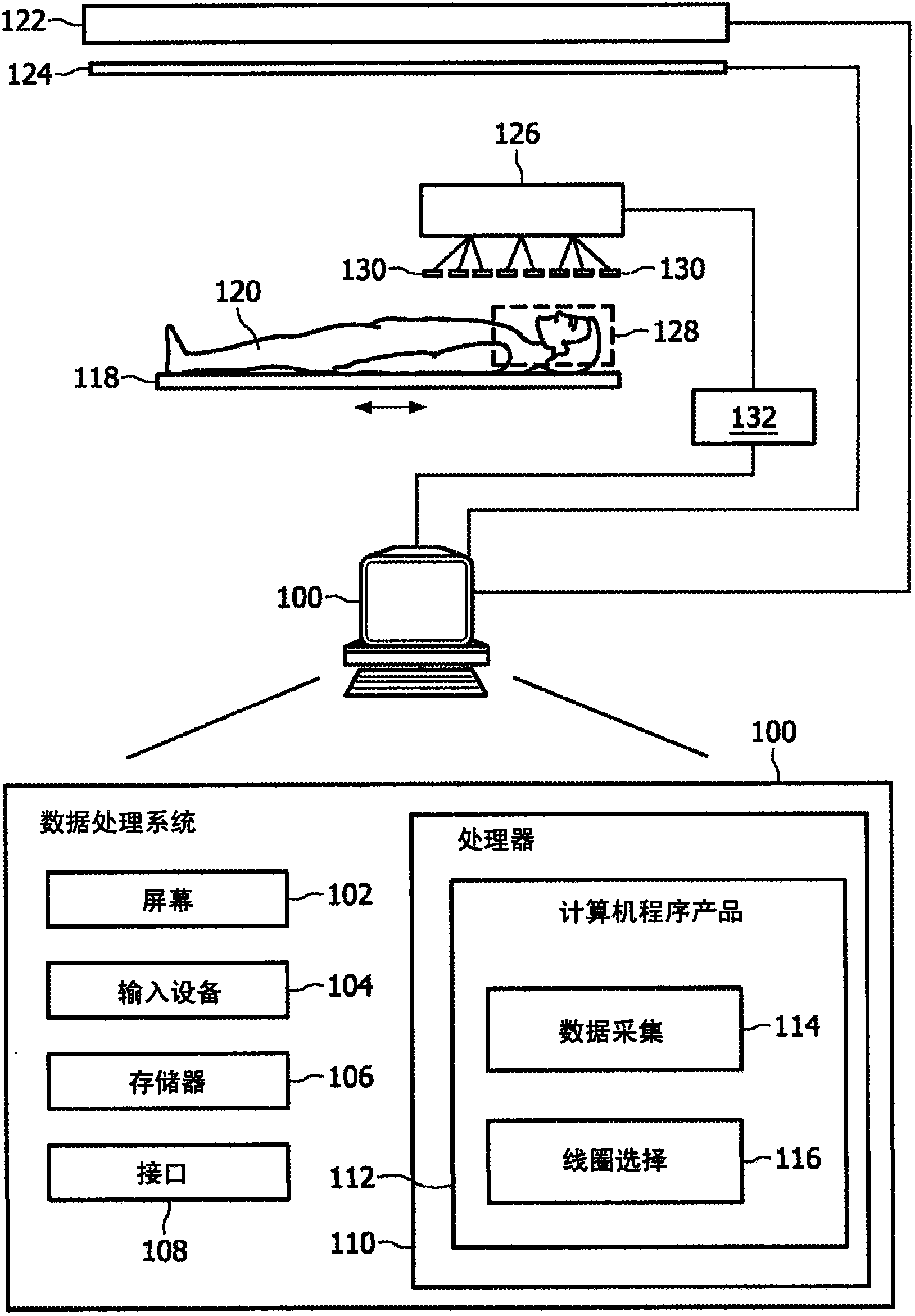
[0051] figure 1 is a schematic diagram showing an MRI system according to the present invention. figure 1 Only the main components of a preferred MRI system incorporating the present invention are shown. The magnetic resonance imaging apparatus includes a data processing system 100 , wherein the data processing system 100 typically includes a computer screen 102 and an input device 104 . Such an input device may be, for example, a keyboard or a mouse.

[0052] figure 1 The MRI system in also includes a memory 106 and an interface 108 . The interface 108 is adapted for communication and data exchange with typical hardware MRI components.

[0053] A typical hardware MRI component is eg a magnet 122 that generates a main magnetic field for performing a magnetic resonance imaging scan of a subject 120 such as a person. Furthermore, the gradient coils 124 are controlled by the data processing system 100, where gradient coils are necessary and are used to perform 3-dimensional ...


PUM


Abstract

The invention relates to a method of selecting a set of coil elements from a multitude of physical coil elements comprised in a coil array for performing a magnetic resonance imaging scan of a region of interest.

Description

technical field [0001] The present invention relates to a method of selecting a set of coil elements from a large number of physical coil elements included in a coil array for performing a magnetic resonance imaging scan, a computer program product and a magnetic resonance imaging system. Background technique [0002] Parallel imaging using a coil array with a large number of individual coil elements provides improved imaging performance and increased signal-to-noise ratio. Today, a basic trend is to greatly increase the number of coil elements used for reception. Recently, 32-element coils have been introduced to boost SNR and allow higher reduction factors (Niendorf T., Hardy C.J., Giaquinto R.O., Gross P., Cline H.E., Zhu Y., Kenwood G., Cohen S., Grant A.K. , Joshi S., Rofsky N.M., Sodickson D.K. (2006) Toward single breath-hold whole-heart coverage coronary MRA using highly accelerated parallel imaging with 32-channel MR system. Magn Reson Med 56:167-176). [0003] Ev...

Claims


Application Information

Patent Timeline
Patent Type & Authority Applications(China)
IPC IPC(8): G01R33/561G01R33/3415
CPCG01R33/5611G01R33/3664G01R33/022G01R33/5659G01R33/543G01R33/3415
Inventor M·P·J·于里森P·博尔纳特M·I·多内瓦M·富德勒
Owner KONINK PHILIPS ELECTRONICS NV
Why Eureka
Try Eureka