

Brake block holder and braking deice
A brake shoe support and support body technology is applied in railway braking systems, brakes with brakes, transportation and packaging, etc. Prevents brake failure, improves safety, and avoids the effect of component shedding
- Summary
- Abstract
- Description
- Claims
- Application Information
AI Technical Summary
Problems solved by technology
Method used
Image

Examples
Embodiment Construction
[0017] In order to make the purpose, technical solutions and advantages of the embodiments of the present invention clearer, the technical solutions in the embodiments of the present invention will be clearly and completely described below in conjunction with the drawings in the embodiments of the present invention. Obviously, the described embodiments It is a part of embodiments of the present invention, but not all embodiments. Based on the embodiments of the present invention, all other embodiments obtained by persons of ordinary skill in the art without creative efforts fall within the protection scope of the present invention.
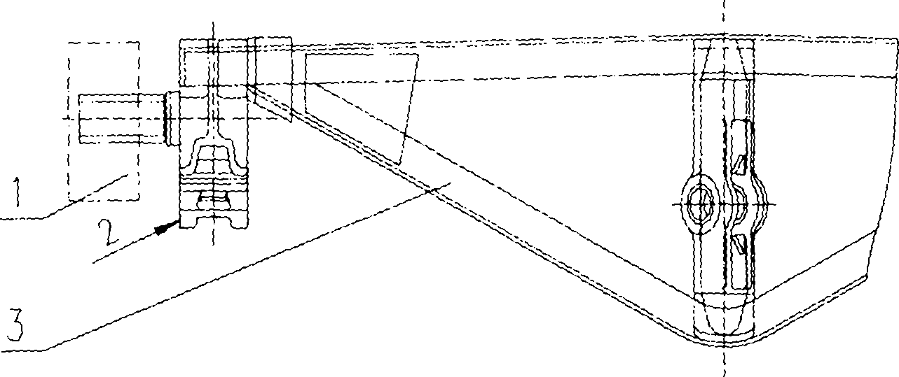
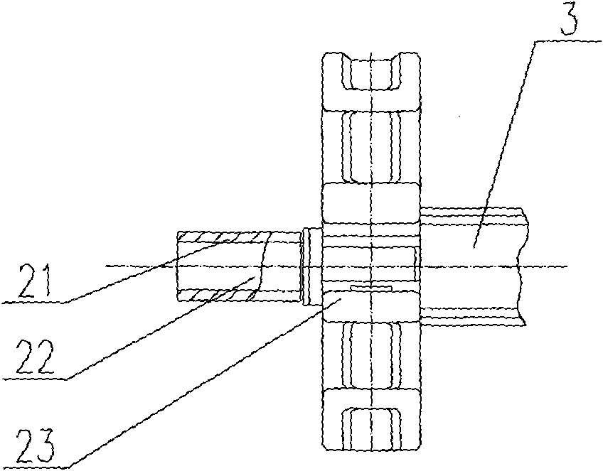
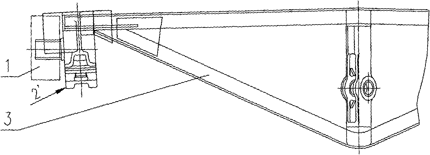
[0018] image 3 The schematic structural diagram of the brake device provided by the embodiment of the present invention, such as image 3 As shown, the brake device is composed of the side frame chute 1 of the bogie, the brake shoe support 2' and the brake beam frame 3. Figure 4 for image 3 Schematic diagram of the upward structure of the br...
PUM
 Abstract
Description
Claims
Application Information