UPS (Uninterrupted Power Supply) power supply control circuit and UPS power supply

A power control circuit and control circuit technology, applied in battery circuit devices, circuit devices, emergency power supply arrangements, etc., can solve the problems of complex UPS power supply circuits and high costs, and achieve the effects of low cost and simple overall circuit.

Active Publication Date: 2011-02-16
EMERSON NETWORK POWER CO LTD
View PDF4 Cites 24 Cited by
  • Summary
  • Abstract
  • Description
  • Claims
  • Application Information

AI Technical Summary

Problems solved by technology

[0009] The technical problem to be solved by the present invention is to provide a UPS power supply for the above-mentioned traditional UPS power supply of the prior art that an independe

Method used


Image

  • UPS (Uninterrupted Power Supply) power supply control circuit and UPS power supply
  • UPS (Uninterrupted Power Supply) power supply control circuit and UPS power supply
  • UPS (Uninterrupted Power Supply) power supply control circuit and UPS power supply

Examples


Embodiment Construction

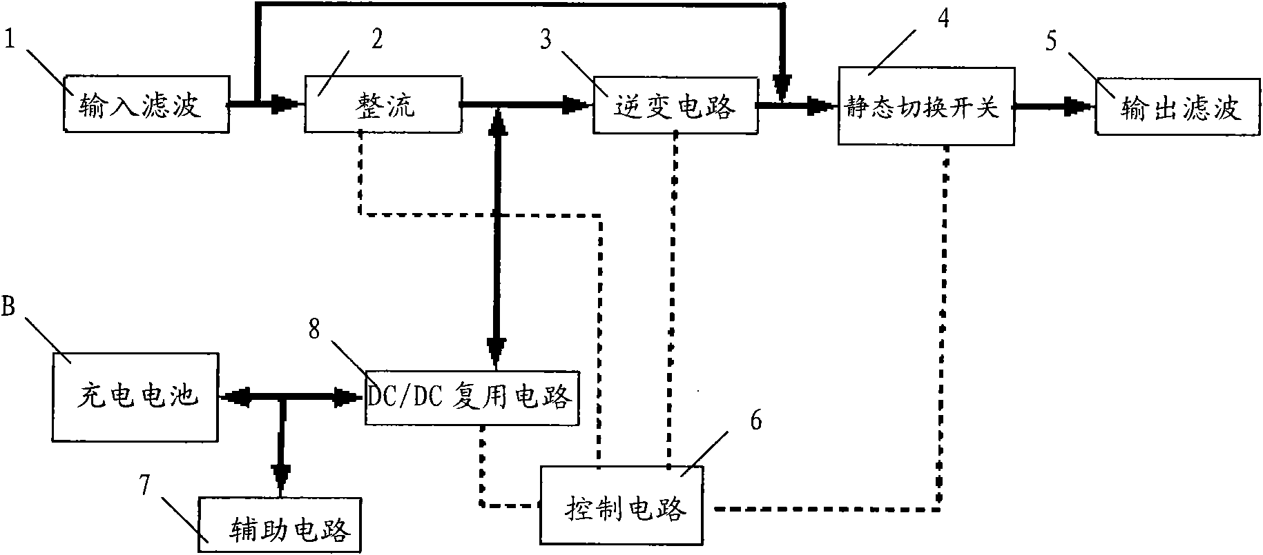
[0052] Such as image 3 Shown is the system block diagram of the UPS power supply of the present invention. The UPS power supply includes a rechargeable battery and a UPS power supply control circuit connected to it. The UPS power supply control circuit includes an input filter circuit 1, a rectifier circuit 2, an inverter circuit 3, a static switch 4, an output filter circuit 5, a control circuit 6, an auxiliary The circuit 7 and the DC / DC multiplexing circuit 8, the input filter circuit 1, the rectifier circuit 2, the inverter circuit 3, the static switch 4 and the output filter circuit 5 are connected in sequence, and the output terminal of the input filter circuit 1 is connected to the static switch 4 connected to the input terminal, the rectifier circuit 2, the inverter circuit 3, the static switch 4 and the DC / DC multiplexing circuit 8 are all connected to the control circuit 6 and controlled by it.

[0053] The DC / DC multiplexing circuit 8 is connected between the outp...


PUM


Abstract

The invention relates to a UPS (Uninterrupted Power Supply) power supply control circuit and a UPS power supply. The UPS power supply comprises a rechargeable battery and the UPS power supply control circuit connected with the rechargeable battery, wherein the UPS power supply control circuit comprises an input filtering circuit, a rectifying circuit, an inverter circuit, a static transfer switch, an output filtering circuit, a control circuit, an auxiliary circuit and a DC (Direct Current)/DC multiplexing circuit connected between the output end of the rectifying circuit and the rechargeablebattery; the DC/DC multiplexing circuit is controlled by the control circuit; the rechargeable battery provides input voltages for the inverter circuit through the DC/DC multiplexing circuit when in a battery supply mode; and the output voltage of the rectifying circuit charges the rechargeable battery through the DC/DC multiplexing circuit when in a main supply mode. Thus, an independent rechargeable circuit is not required to charge the rechargeable battery, and the UPS power supply control circuit has the advantages of simple integral circuit, low cost and great value for clients.

Description

technical field [0001] The present invention relates to the field of power supply, more specifically, to a UPS power supply control circuit and UPS power supply. Background technique [0002] In traditional UPS power supplies, there are generally two designs of chargers: [0003] The first type, isolated type, generally adopts flyback conversion, and some also use double forward conversion, etc.; [0004] The second type is non-isolated type, which uses BUCK circuit step-down, BUCK-BOOST circuit step-down conversion, etc. [0005] The design idea of ​​the above-mentioned traditional UPS charger is that the charger is set independently. In the UPS power supply, no matter how the charger is connected to the UPS system, the charger is an independent component of the UPS system. [0006] like figure 1 Shown is the first system block diagram of the traditional UPS power supply. This UPS power supply includes input filter circuit 1, rectifier circuit 2, inverter circuit 3, stat...

Claims


Application Information

Patent Timeline
IPC IPC(8): H02J7/00H02J7/02
CPCH02J2009/067H02J9/061H02J7/0068H02M3/337H02J9/067H02M3/33573H02M3/01
Inventor 倪同
Owner EMERSON NETWORK POWER CO LTD
Why Eureka
Try Eureka