
Controller and adjustment and control method for controller

A controller and transformer technology, which is applied to control/regulating systems, instruments, adjusting electrical variables, etc., can solve the problems of falling off, power consumption of the control chip 100, affecting use, etc., to avoid the effect of restarting the state

Active Publication Date: 2011-02-16
BCD (SHANGHAI) MICRO ELECTRONICS LTD
View PDF5 Cites 15 Cited by
  • Summary
  • Abstract
  • Description
  • Claims
  • Application Information

AI Technical Summary

Problems solved by technology

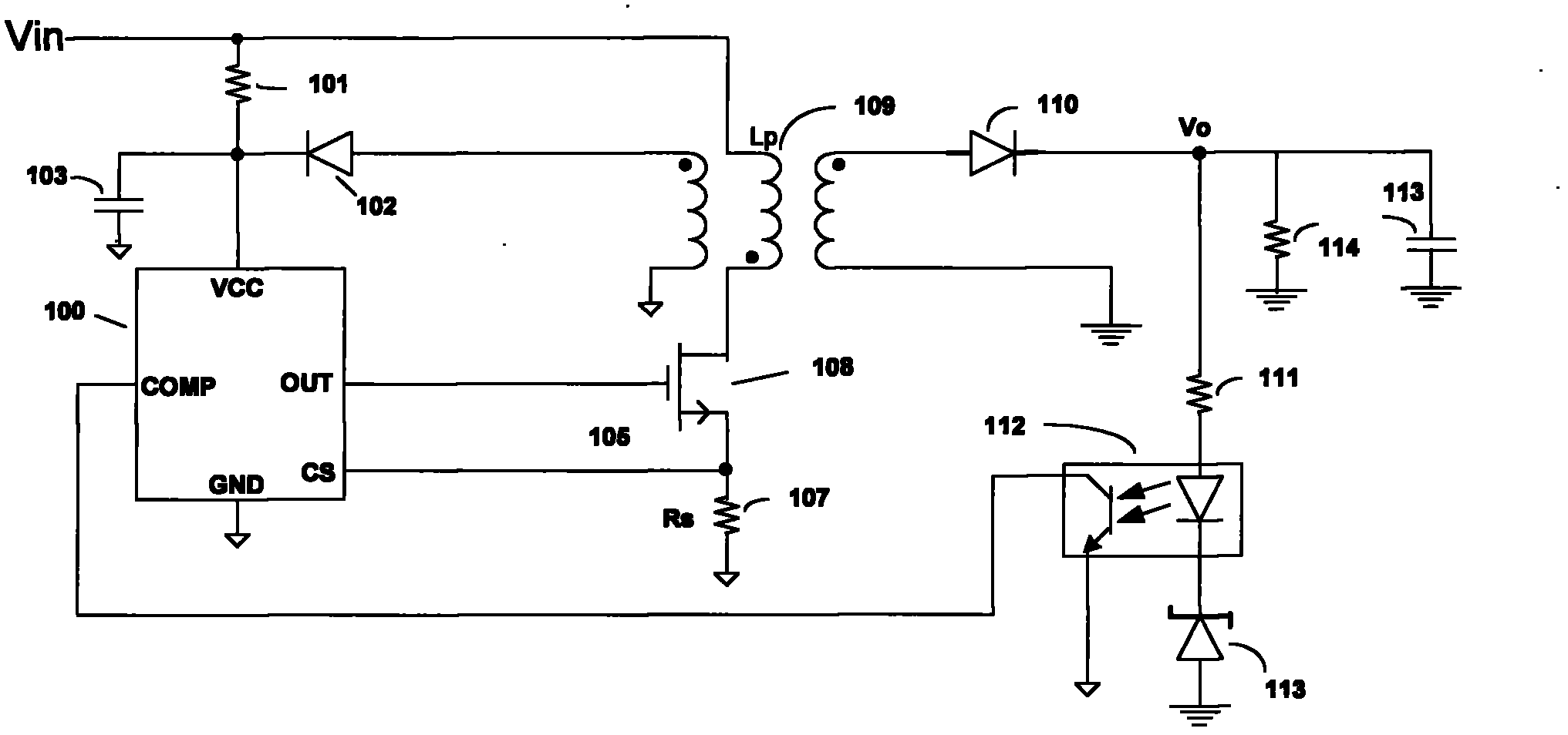
[0004] When the controller works in the light-load frequency hopping mode, the control chip 100 does not output PWM waveforms, and the auxiliary winding of the transformer 109 no longer supplies power to the power supply capacitor 103. Although there is no switching loss at this time, there is power consumption inside the control chip 100, so the control The power supply voltage VCC of the chip 100 starts to drop
Generally, the time constant of the power supply capacitor 103 is smaller than the time constant of the output capacitor 113, so the power supply voltage VCC drops faster. When the power supply voltage VCC is lower than the undervoltage lockout level (UVLO), the controller restarts state, affect the use of

Method used


Image

  • Controller and adjustment and control method for controller
  • Controller and adjustment and control method for controller
  • Controller and adjustment and control method for controller

Examples


Embodiment Construction

[0032] The following will clearly and completely describe the technical solutions in the embodiments of the present invention with reference to the accompanying drawings in the embodiments of the present invention. Obviously, the described embodiments are only some of the embodiments of the present invention, not all of them. Based on the embodiments of the present invention, all other embodiments obtained by persons of ordinary skill in the art without creative efforts fall within the protection scope of the present invention.

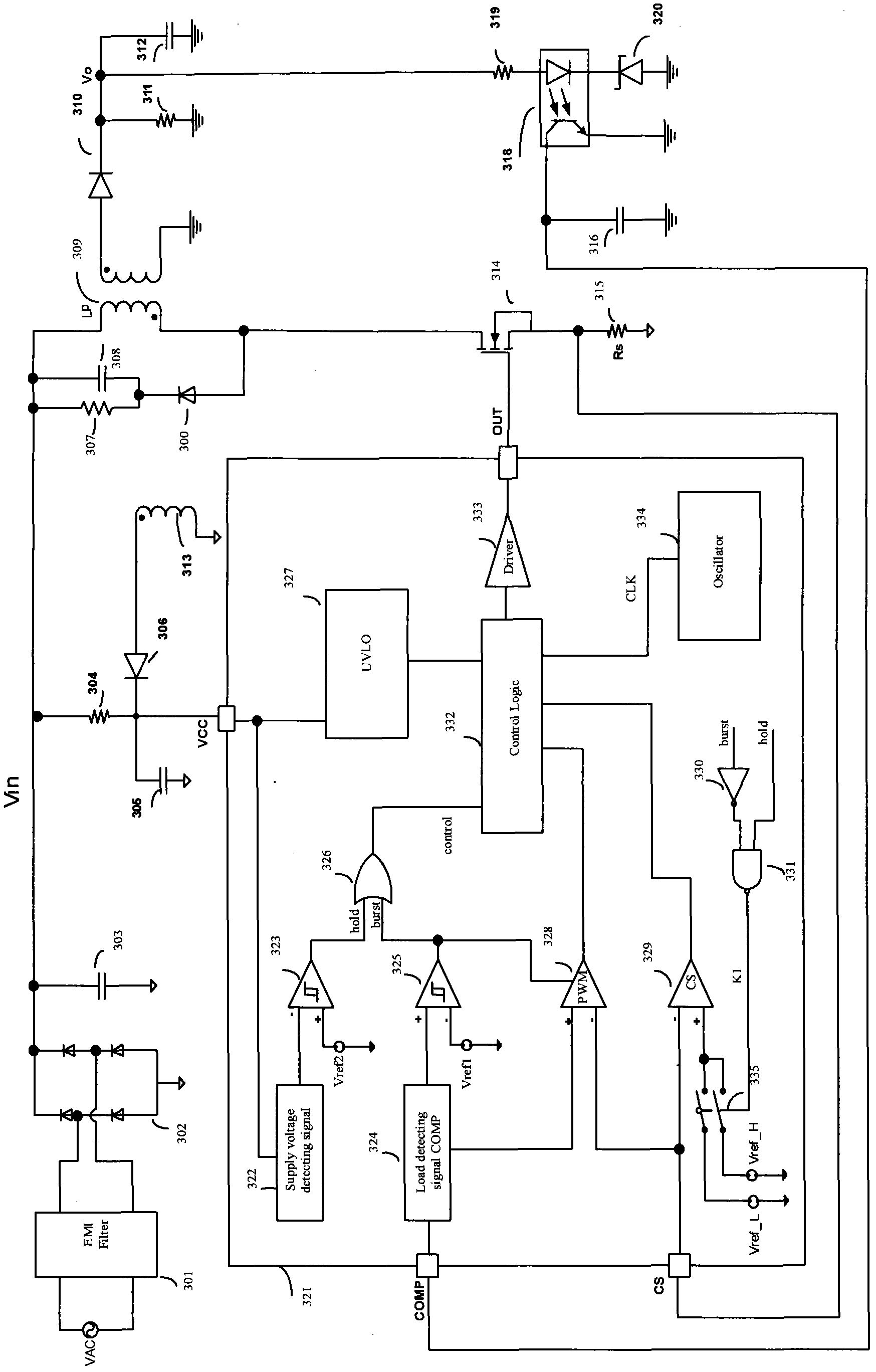
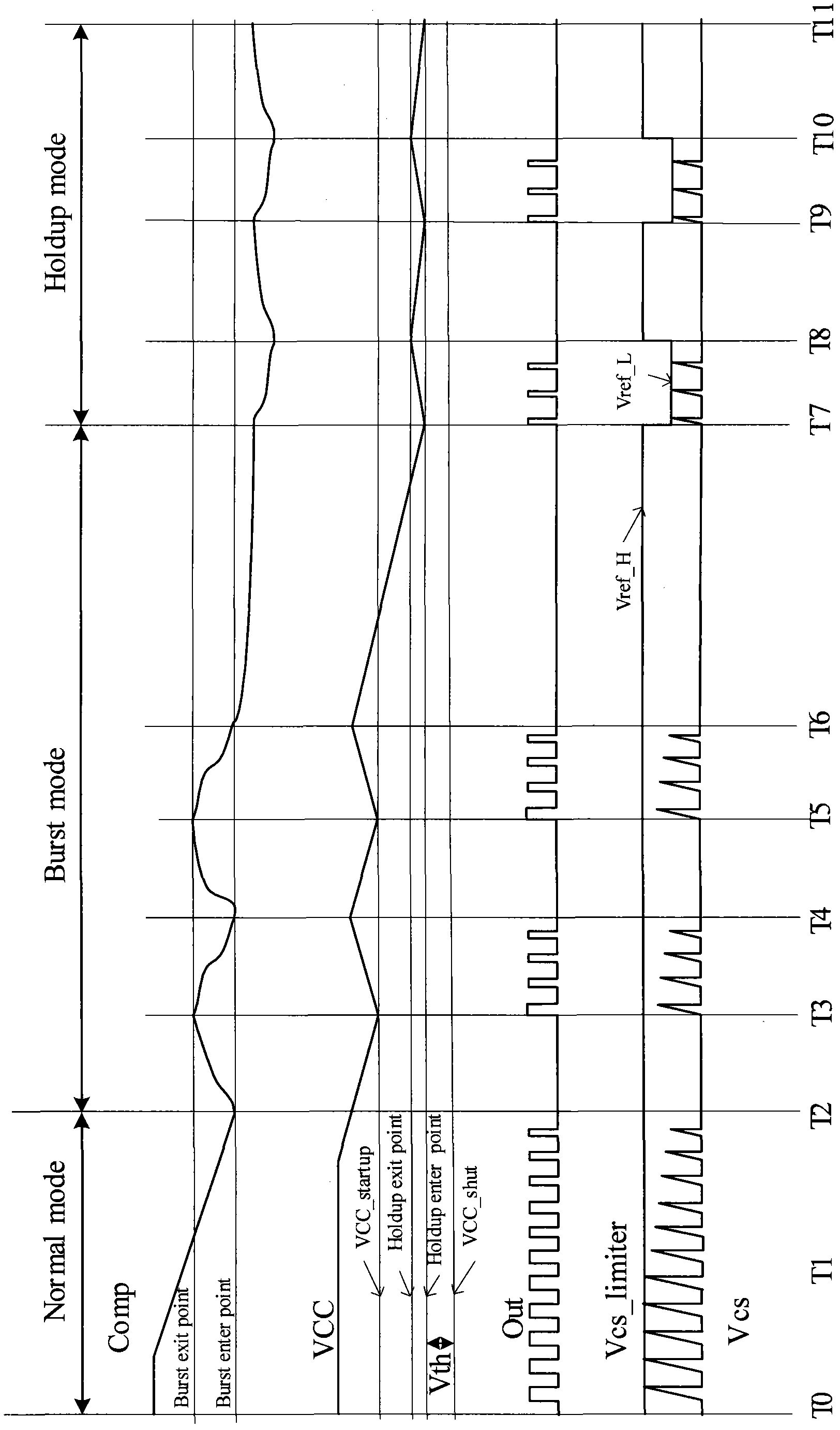
[0033] The present invention determines the load state through the detected COMP signal, and detects the power supply voltage VCC at the same time. On the one hand, the voltage threshold is set for the power supply voltage VCC, and on the other hand, the light load threshold is set. It is detected that the power supply voltage VCC is less than the voltage threshold. In the state of load, the controller works in holdup mode and outputs relatively narrow...


PUM


Abstract

The invention discloses a controller. The controller comprises a switch tube, a first hysteresis comparator, a second hysteresis comparator, a pulse width modulation (PWM) comparator, a control signal (CS) comparator, an or gate and a logic controller, wherein the switch tube controls work of a transformer; the first hysteresis comparator compares a comparator (COMP) signal with load threshold value Vref1 and outputs a burst signal; the second hysteresis comparator compares a source voltage VCC with a power threshold value Vref2 and outputs a hold signal; a control end of the PWM comparator is connected with the burst signal, and an output end is connected with the logic controller; an output end of the CS comparator is connected with the logic controller; two input ends of the or gate are connected with the hold signal and the burst signal respectively and output a control signal (control) to the logic controller; the logic controller controls the switch tube; and when COMP is less than Vref1 and VCC is less than Vref2, the controller works in a holdup mode, the PWM comparator is shielded, the comparison level of the CS comparator is low level, and the switch tube has output and keeps the power voltage VCC over under-voltage locking voltage. The invention also discloses an adjustment and control method for the controller. The adjustment and control method has a good power-saving effect.

Description

technical field [0001] The invention relates to the technical field of controllers, more specifically, to a controller capable of reducing static loss under light load conditions and a control method based on the controller. Background technique [0002] When the controller works under light load conditions, the operating frequency will generally be reduced to reduce switching losses. When the load is further reduced, or even there is no load, and the controller does not output PWM waveforms, it generally no longer supplies power to the control chip. Although there is no switching loss at this time, there is power consumption inside the control, so the power supply voltage of the control chip starts When it drops to undervoltage, the control chip starts to lock the level, so that the controller enters the restart state. [0003] see figure 1 , showing the existing controller structure. Among them, the control chip 100 is included, the optocoupler 112 transmits the COMP si...

Claims


Application Information

Patent Timeline
IPC IPC(8): H02M7/12H02M3/335
Inventor 应征王美娟赵向源
Owner BCD (SHANGHAI) MICRO ELECTRONICS LTD
Learn More