Ventilator arrangement for gravitational fluid discharge via high and low pressure phase

A technology of pressure and structure, applied in the field of valve structure used to discharge liquid through gravity under overpressure and negative pressure, can solve the problem that the system cannot be emptied, and achieve low structural height, small structural space requirements, low cost effect

Inactive Publication Date: 2011-02-23
EVAC GMBH
View PDF0 Cites 6 Cited by
  • Summary
  • Abstract
  • Description
  • Claims
  • Application Information

AI Technical Summary

Problems solved by technology

[0006] Another problem is that such systems cannot be emptied

Method used


Image

  • Ventilator arrangement for gravitational fluid discharge via high and low pressure phase
  • Ventilator arrangement for gravitational fluid discharge via high and low pressure phase
  • Ventilator arrangement for gravitational fluid discharge via high and low pressure phase

Examples


Embodiment Construction

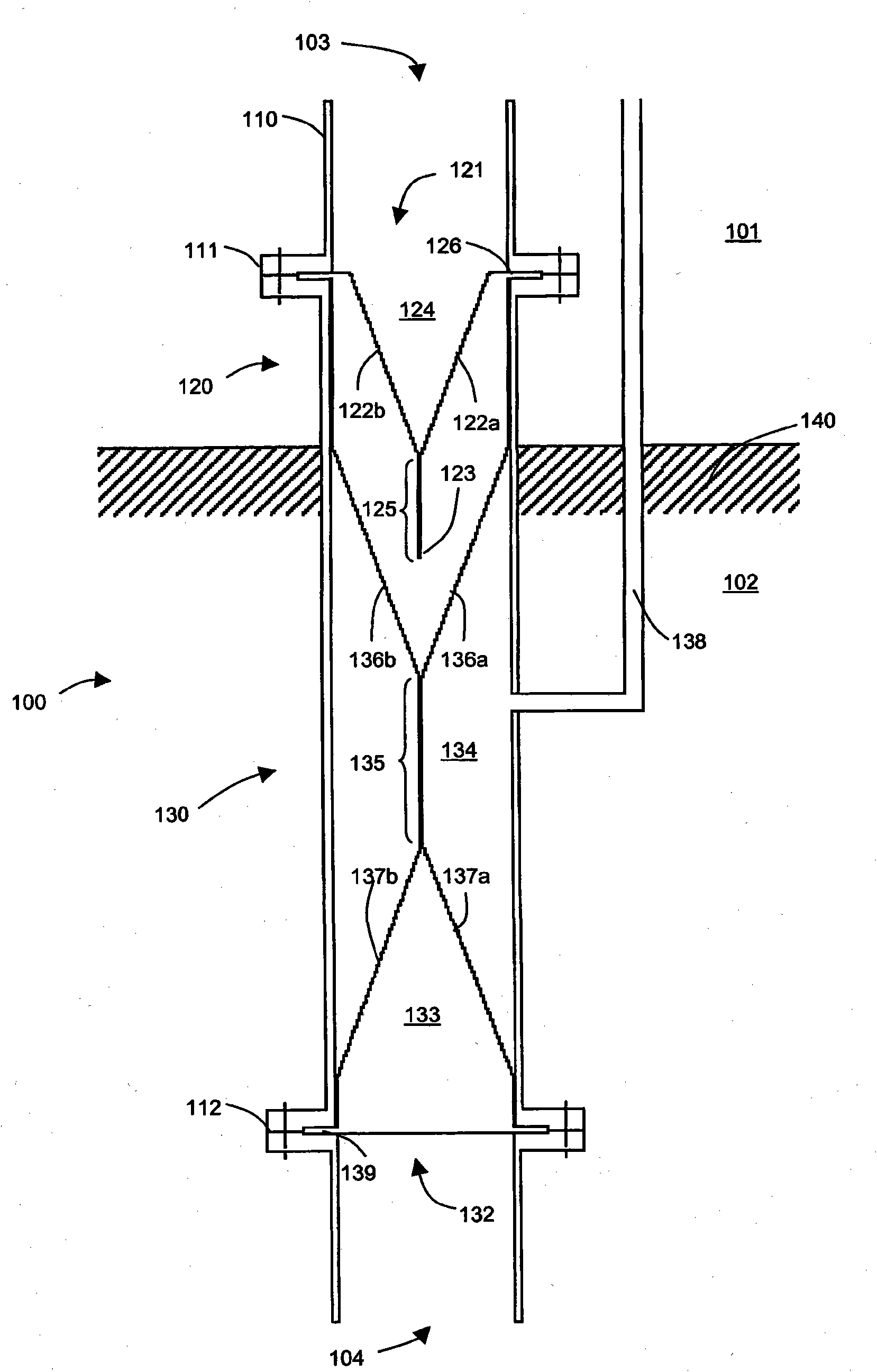
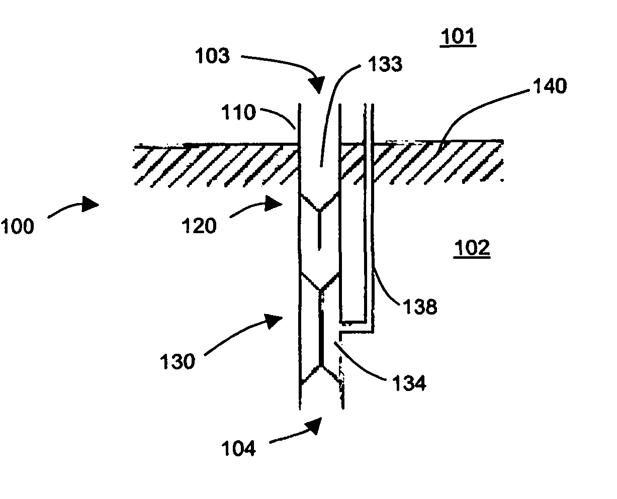
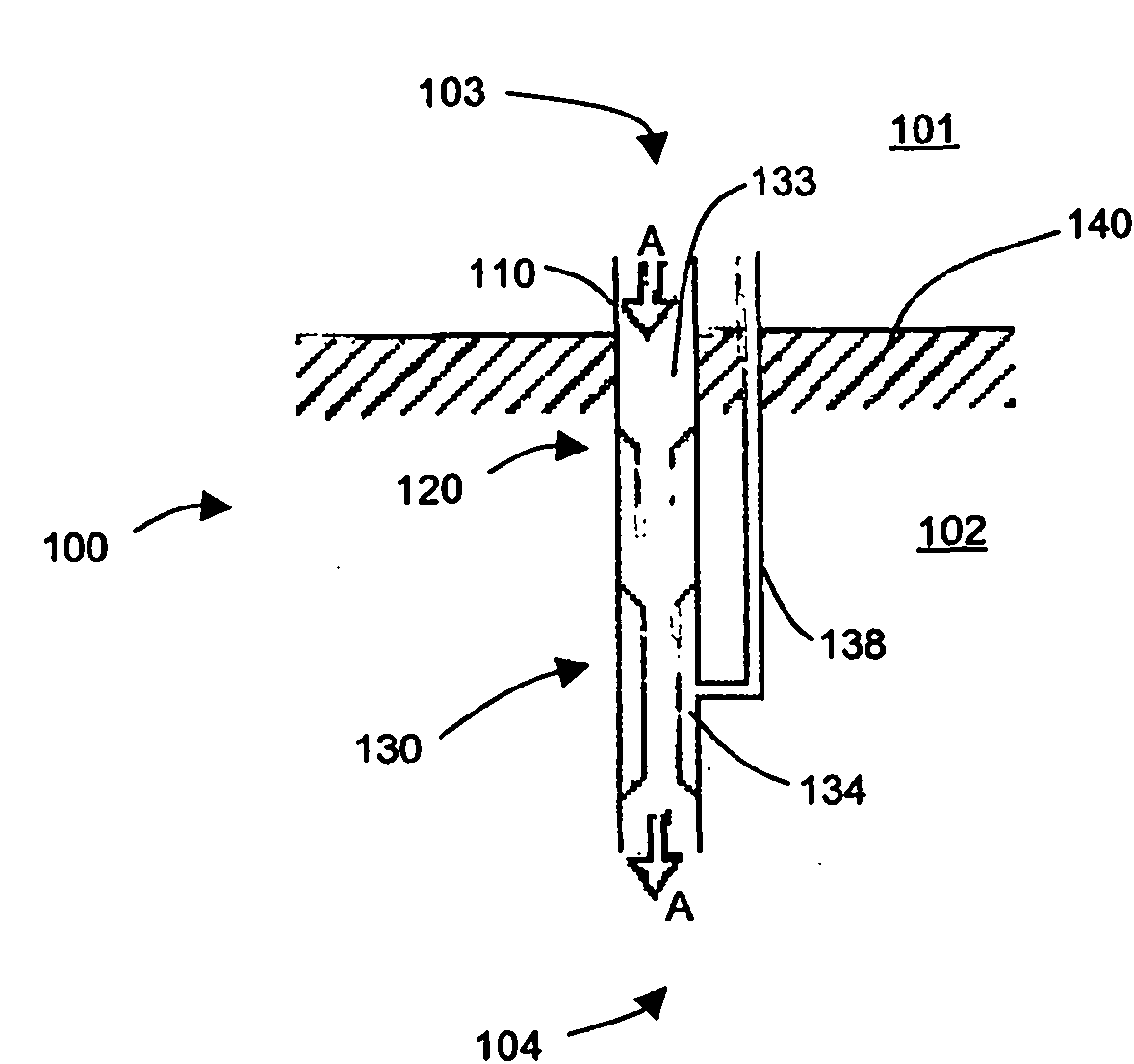
[0080] figure 1 A longitudinal sectional view of a first embodiment of a valve arrangement 100 according to the invention is shown for discharging a liquid medium from a space 101 which is pressure-damaged with respect to the environment 102 into the environment 102 . The valve configuration 100 has an inlet 103 and an outlet 104 . The pressure-attenuated space 101 is separated from the external environment 102 by a partition 140 such as the bottom of a railway car. The air pressure in the pressure-attenuated space 101 corresponds to the air pressure in the external environment 102 .

[0081] The inlet 103 is connected to the outlet 104 through a connecting pipe 110 . The same air pressure prevails at the inlet 103 as in the environment 102 . The valve configuration 100 is mounted such that a liquid medium can flow from the inlet 103 to the outlet 104 in the direction of gravity.

[0082] The valve arrangement 100 has a non-return valve 120 and a shut-off valve 130 . The ...


PUM


Abstract

The invention relates to a device for discharging a fluid medium from a space (101), which is pressure-damped as opposed to an environment, into the environment (102). The invention further relates to a valve arrangement for discharging a fluid medium from a space, which is pressure-damped as opposed to an environment, into the environment, comprising an inlet opening (103), which is in gas pressure contact with the pressure-damped space in the installed position, an outlet opening (104) positioned below the inlet opening in the installed position in the direction of gravity, said outlet opening being in gas pressure contact with the environment in the installed position, a connecting channel (110) connecting the inlet opening to the outlet opening, a return flow stop valve (120), which is configured in order to allow the fluid medium to pass from the inlet opening to the outlet opening under the influence of gravity, and in order to close it off if a predetermined gas overpressure present in the environment as opposed to the pressure-damped space is exceeded, a through-flow stop valve (130), which is configured to allow the fluid medium to pass from the inlet opening to the outlet opening under the influence of gravity, and to close it off if a predetermined gas overpressure present in the pressure-damped space as opposed to the environment is exceeded.

Description

technical field [0001] The invention relates to a device for discharging a liquid medium from a space attenuated in pressure relative to the environment into the environment. [0002] In this case, a pressure-damaged space is understood to be a space that is completely, however at least substantially closed from the environment, but which can also have closable openings, such as doors and windows in railway carriages. In this application, pressure decay is understood to mean that, at least for a short time, a pressure difference can occur between the pressure-decaying space and the environment. Background technique [0003] In devices of the aforementioned kind, problems often arise in the area of ​​the liquid discharge line in the event of a pressure difference between the pressure-damped space and the external environment. If the pressure-decaying space is, for example, a high-speed train carriage, a short-term pressure difference typically occurs when entering a tunnel o...

Claims


Application Information

Patent Timeline
Patent Type & Authority Applications(China)
IPC IPC(8): E03F1/00F16K15/14B61D35/00
CPCE03C1/298B61D35/007F16K15/147
Inventor 托比亚斯·霍恩
Owner EVAC GMBH
Why Eureka
Try Eureka