Nuclear gauges and methods of configuration and calibration of nuclear gauges

A measuring instrument, nuclear technology, applied in the direction of measuring devices, test/calibration devices, equipment with stored calibration coefficients, etc., can solve problems such as time-consuming

Inactive Publication Date: 2011-02-23
TROXLER ELECTRONICS LAB INC
View PDF6 Cites 18 Cited by
  • Summary
  • Abstract
  • Description
  • Claims
  • Application Information

AI Technical Summary

Problems solved by technology

[0011] Also, it is well known in the art that calibration of nuclear gauges (such as 12-pos

Method used


Image

  • Nuclear gauges and methods of configuration and calibration of nuclear gauges
  • Nuclear gauges and methods of configuration and calibration of nuclear gauges
  • Nuclear gauges and methods of configuration and calibration of nuclear gauges

Examples


Embodiment Construction

[0048] Reference will now be made in detail to the description of the present subject matter, one or more examples of which are illustrated in the accompanying drawings. Each example is provided by way of illustration of a topic, not limitation. In fact, features shown or described as part of one example can be used in another example to yield still further examples. It is hoped that this topic covers these modifications and changes.

[0049] Nuclear Gauge Device

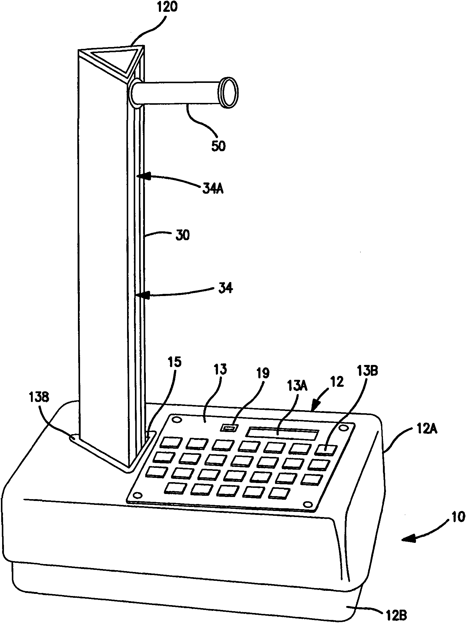
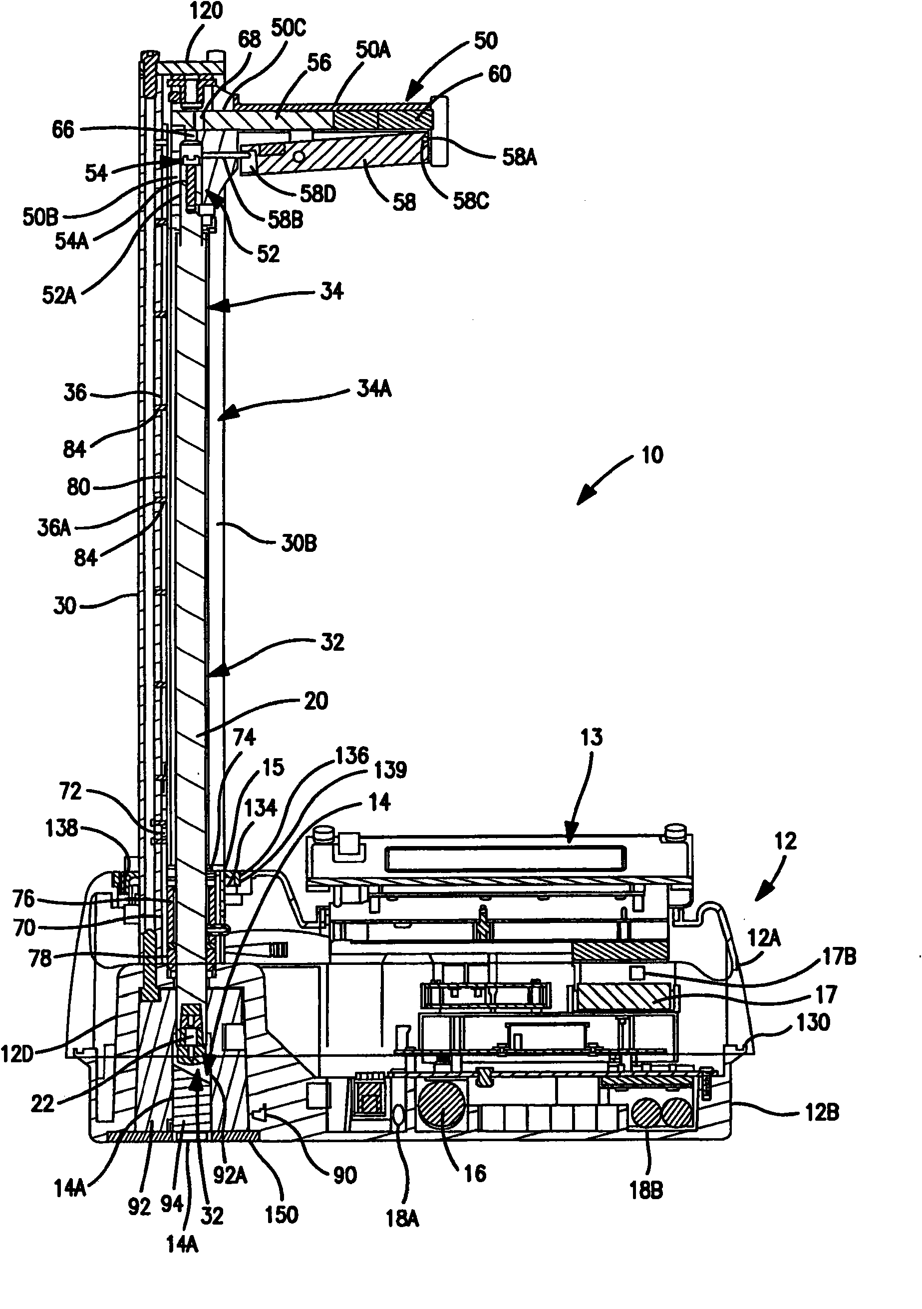
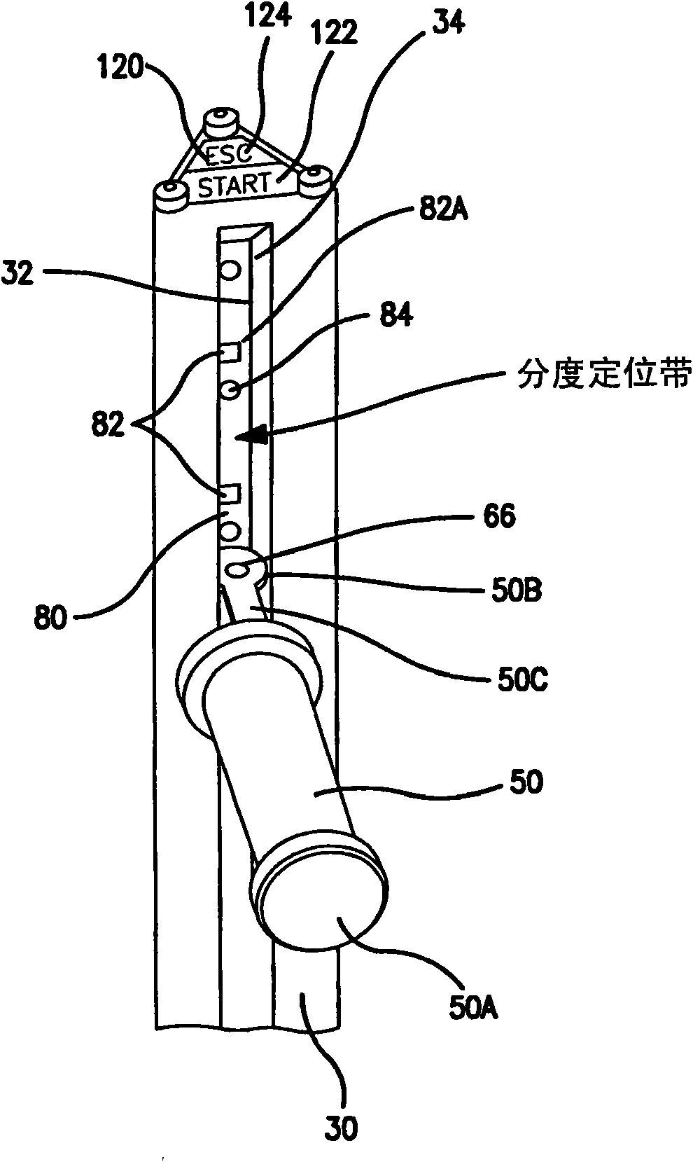
[0050] figure 1 with figure 2 A gauge generally designated 10 is shown. This document provides a brief description of the various aspects and components of the gauge 10, with more detailed descriptions of the various elements described further below. The nuclear gauge may be a density gauge, a bulk density gauge, a thin overburden gauge, a thin ply gauge, or a combination thereof.

[0051] To illustrate the subject matter by way of example, the meter 10 in the figure is a thin-ply meter. However, as noted ...


PUM


Abstract

Nuclear gauges and method of configuration and methods of calibrations of the nuclear gauges are provided. The nuclear gauges are used in measuring the density and/or moisture of construction-related materials. The nuclear gauge can include a gauge housing having a vertical cavity therethrough and at least one radiation detector located within the housing. The nuclear gauge can include a vertically moveable source rod and a radiation source operatively positioned within a distal end of the source rod.

Description

[0001] Cross References to Related Applications [0002] The presently disclosed subject matter claims the benefit of US Provisional Patent Application Serial Nos. 61 / 010,103, 61 / 010,022, and 61 / 010,191, all filed January 4, 2008. The aforementioned Provisional Patent Application is hereby incorporated by reference in its entirety. technical field [0003] The subject matter generally relates to instruments and methods for determining density and / or moisture of materials, and more particularly to nuclear gauges for measuring density and / or moisture of construction materials. Background technique [0004] Nuclear radiation measuring instruments are widely used in the determination of the density and moisture content of soil and asphalt materials or other construction materials. As used herein, construction material refers to any material used in the construction of roads or foundation works, including but not limited to: soil, asphalt, asphalt-like materials, concrete, compo...

Claims


Application Information

Patent Timeline
IPC IPC(8): G01N23/20G01N23/02G08C19/00G01N9/24
CPCG01D18/008G01N23/09Y10T29/49826G01N23/06G01N23/203G01T7/005
Inventor D·E.·韦格D·M.·斯特克曼R·E·特罗克斯勒
Owner TROXLER ELECTRONICS LAB INC
Why Eureka
Try Eureka