Regulator for train brake pad

A technology of brake pads and adjusters, applied in the direction of brake parts, etc., can solve the problems of limited effect of adjusting friction blocks, inconvenient installation, complex structure, etc.

Active Publication Date: 2011-03-02
CRRC CHANGZHOU TECH MARK IND CO LTD +1
View PDF8 Cites 7 Cited by
  • Summary
  • Abstract
  • Description
  • Claims
  • Application Information

AI Technical Summary

Problems solved by technology

However, the existing adjuster for train brake pads has a complex structure, is

Method used


Image

  • Regulator for train brake pad
  • Regulator for train brake pad
  • Regulator for train brake pad

Examples


Embodiment Construction

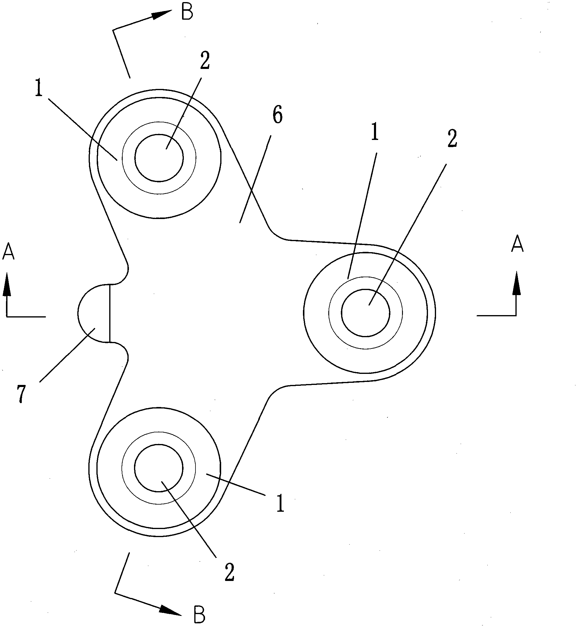
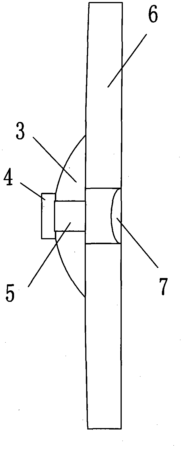
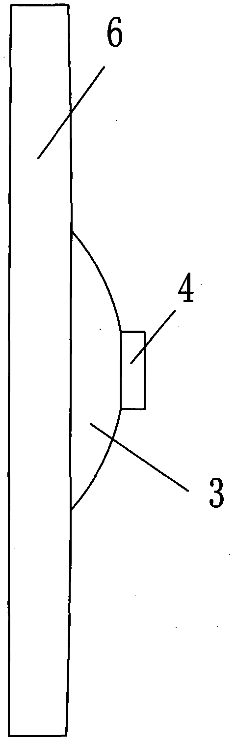
[0015] Such as Figure 1-7 As shown, the train brake pad adjuster of the present invention comprises a bearing plate 6, an adjuster ball cup 1 and an adjuster spherical body 3, the adjuster ball cup 1 is arranged on the bearing plate 6, and the adjuster ball cup 1 bottom There is a through hole 2, and the lower part of the bearing plate 6 has an adjuster spherical body 3, and also includes a mounting boss 4 and an adjuster positioning convex pin 5; the mounting boss 4 is located at the lower end of the adjuster spherical body 3; the adjustment The device positioning lug 5 is located at the lower part of the bearing plate 6; the bearing plate 6 is in the shape of three leaf petals, and there is an adjuster ball cup 1 on each leaf petal, that is, there are three adjuster ball cups 1, and the two leaf petals The root between them has a radial projection 7, and the axial direction of the radial projection 7 is provided with an adjuster positioning protrusion 5; the bottom surface ...


PUM


Abstract

The invention discloses a regulator for a train brake pad, comprising a bearing plate, a regulator ball cup and a regulator spherical body, wherein the regulator ball cup is arranged on the bearing plate, the bottom of the regulator ball cup is provided with through holes, and the lower part of the bearing plate is provided with the regulator spherical body. The regulator also comprises an installation boss and a regulator positioning convex pin, wherein the installation boss is arranged on the lower end of the regulator spherical body, the regulator positioning convex pin is arranged on the lower part of the bearing plate which is in a three-leaf petal shape, each petal is provided with one regulator ball cup, the root between two petals is provided with a radial bulge, and the axial direction of the radial bulge is provided with the regulator positioning convex pin; and the bottom of the bearing plate is gradually and upwards inclined from inside to outside, i.e. the thickness of the wall of the bearing plate is gradually decreased from inside to outside. The invention has simple structure and is convenient to install; when a friction block is regulated, the regulator has good elasticity and good regulation effect and has the action on shock absorption and noise reduction.

Description

technical field [0001] The invention relates to a train brake pad, in particular to a component of a train brake pad. Background technique [0002] With the trend of high-speed development of trains, higher requirements are put forward for train braking. Today's high-speed train brake pads have adopted a brake pad structure with an adjuster, so that the brake pads can automatically adjust each friction block on the adjuster to the same plane under high-speed and high-pressure braking conditions to improve contact during work. area, reduce overheating fatigue, improve the heat dissipation capacity of the brake pads, and overcome the decline of friction performance of the brake pads. However, the existing adjuster for train brake pads has a complex structure, is inconvenient to install, and has limited effect when adjusting the friction block. Contents of the invention [0003] The purpose of the present invention is to provide a train brake pad adjuster with simple struct...

Claims


Application Information

Patent Timeline
IPC IPC(8): F16D65/04
Inventor 李岫王磊何延楠郑剑云刘颖
Owner CRRC CHANGZHOU TECH MARK IND CO LTD
Why Eureka
Try Eureka