Device and method for producing bags

A pocket and conveying direction technology, applied in packaging, bag making operations, transportation and packaging to minimize mechanical costs

Active Publication Date: 2011-03-02
WINDMOELLER & HOELSCHER GMBH
View PDF6 Cites 3 Cited by
  • Summary
  • Abstract
  • Description
  • Claims
  • Application Information

AI Technical Summary

Problems solved by technology

This time space may even be an upper bound on the efficiency of the above devices for processing pockets

Method used


Image

  • Device and method for producing bags
  • Device and method for producing bags
  • Device and method for producing bags

Examples


Embodiment Construction

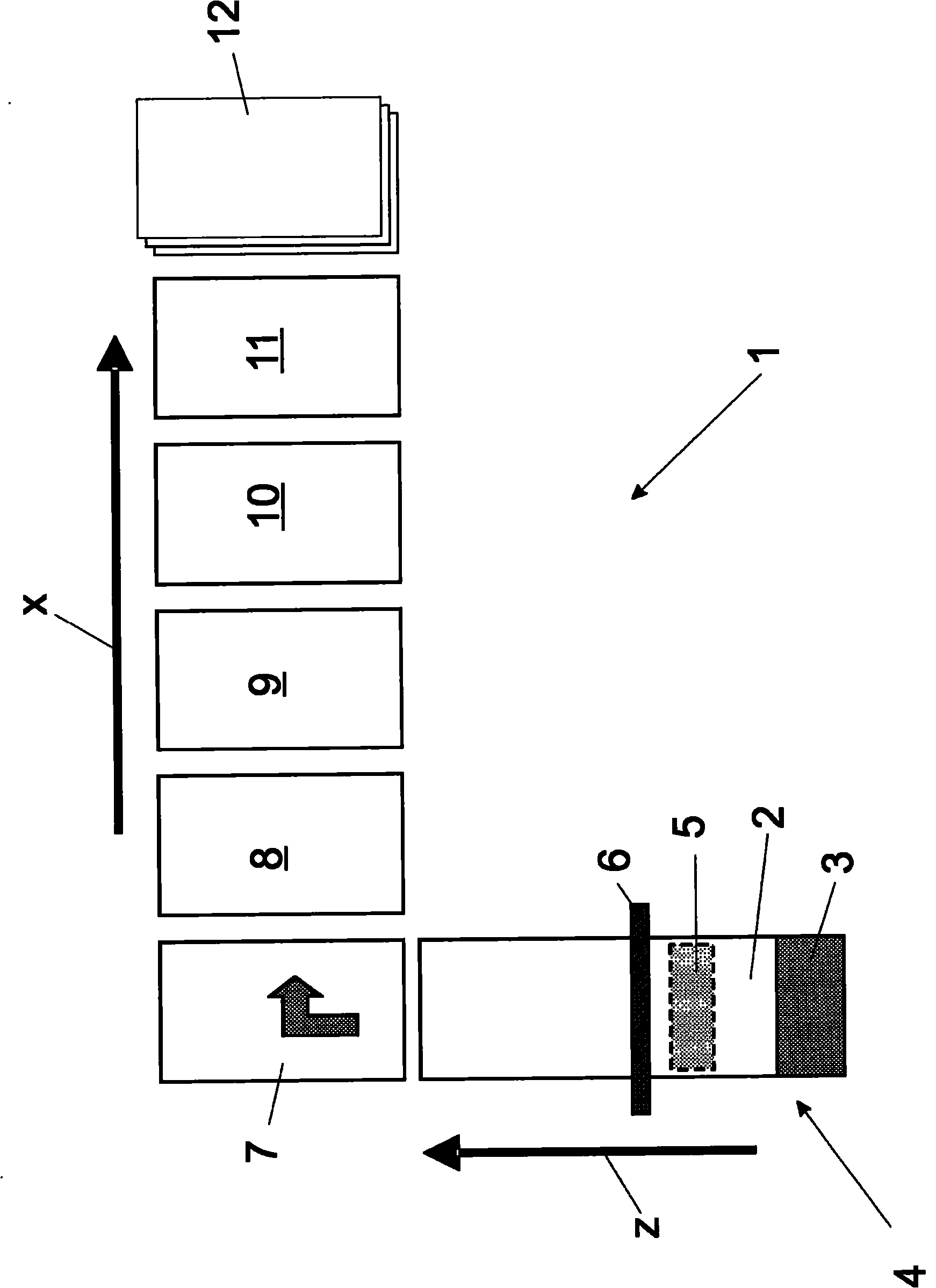
[0030] figure 1 The individual steps for processing the textile tube into a bag are briefly shown, how they are carried out in the bag processing device 1 .

[0031] The fabric tube 2 is first conveyed to the bag processing device 1 . This is advantageously achieved in the unwinding device 4 by unwinding the textile hose forming the reel 3 . The hose 2 is then so-called opened at the layering station 5 . Here, the textile hose is guided around an inner mold which separates the two layers from each other and thus separates the layers if they were already glued to each other during the processing step of the hose. Only for the separated layers can it be ensured that subsequent production steps are carried out in an orderly manner. The separate layers of hose material are then laid on top of each other.

[0032] The textile hose is now fed to the transverse cutting device 6 , which subdivides the textile hose into individual hose sections.

[0033] Then the original conveyin...


PUM


Abstract

The invention relates to a device for producing bags (1) from pieces (13) of tubing which can be transported in a transport direction (x) transversally to the longitudinal direction of the pieces of tubing by means of the device (1). The pieces (13) of tubing preferably comprise a fabric consisting of stretched plastic strips (2) and consist of two layers of material arranged one above the other. The device comprises the following components: at least one element (8) for opening an end (13) of a piece of tubing, by which means part of the end of the piece of tubing can be folded back onto a wall of the piece of tubing in order to open the end, such that said opened end can be attached to a bottom; and at least one pressure means for pressing at least parts of the opened end against a counter-layer in order to form fold edges. At least one transport means (30) is used to transport the piece of tubing in the direction of transport (x) once an end of said piece of tubing has been opened and before the action of the pressure means.

Description

technical field [0001] The invention relates to a device for processing sacks according to the preamble of claim 1 , through which the sacks are conveyed perpendicularly to their length, and to a method according to the preamble of claim 14 . Background technique [0002] Such devices are known and have long been available on the market. They generally mainly include subdivision means for subdividing the incoming hose into hose sections. This hose preferably consists of a fabric made of stretched small plastic strips, which may also be covered. A subdivided hose section consists of two material strips located one above the other. After subdivision, at least one conveying device receives the hose sections for transporting them to the individual processing stations. One such processing station is a so called open bottom station. At least one end of the hose section is raised here, so that a base can be formed at this raised end. Usually both ends of the hose section are t...

Claims


Application Information

Patent Timeline
Patent Type & Authority Applications(China)
IPC IPC(8): B31B1/76B31B29/00B31B50/76B31B70/04
CPCB31B29/00B31B2221/405B31B2219/28B31B2221/20B31B70/00B31B70/003B31B2150/00B31B2150/0014B31B2160/10B31B2160/20
Inventor C·黑格尔C·陶施
Owner WINDMOELLER & HOELSCHER GMBH
Why Eureka
Try Eureka