Motor control method, motor control device, fan device, compressor, and pump device

A control device and control method technology, applied in the direction of single motor speed/torque control, electronic commutator, etc., can solve problems such as speed instability, achieve the effects of improving efficiency, avoiding excessive shortening of intervals, and reducing detection errors

Active Publication Date: 2011-03-02
DAIKIN IND LTD
View PDF4 Cites 0 Cited by
  • Summary
  • Abstract
  • Description
  • Claims
  • Application Information

AI Technical Summary

Problems solved by technology

In the technology described in Patent Document 1, especially when the rotation speed is high, due to the deviation of the position signal, for example, among the three-phase operating currents supplied to the three-phase motor, the operating current of one phase may be larger than the operating current of the other phases. Therefore, the speed is unstable

Method used


Image

  • Motor control method, motor control device, fan device, compressor, and pump device
  • Motor control method, motor control device, fan device, compressor, and pump device
  • Motor control method, motor control device, fan device, compressor, and pump device

Examples


no. 1 approach

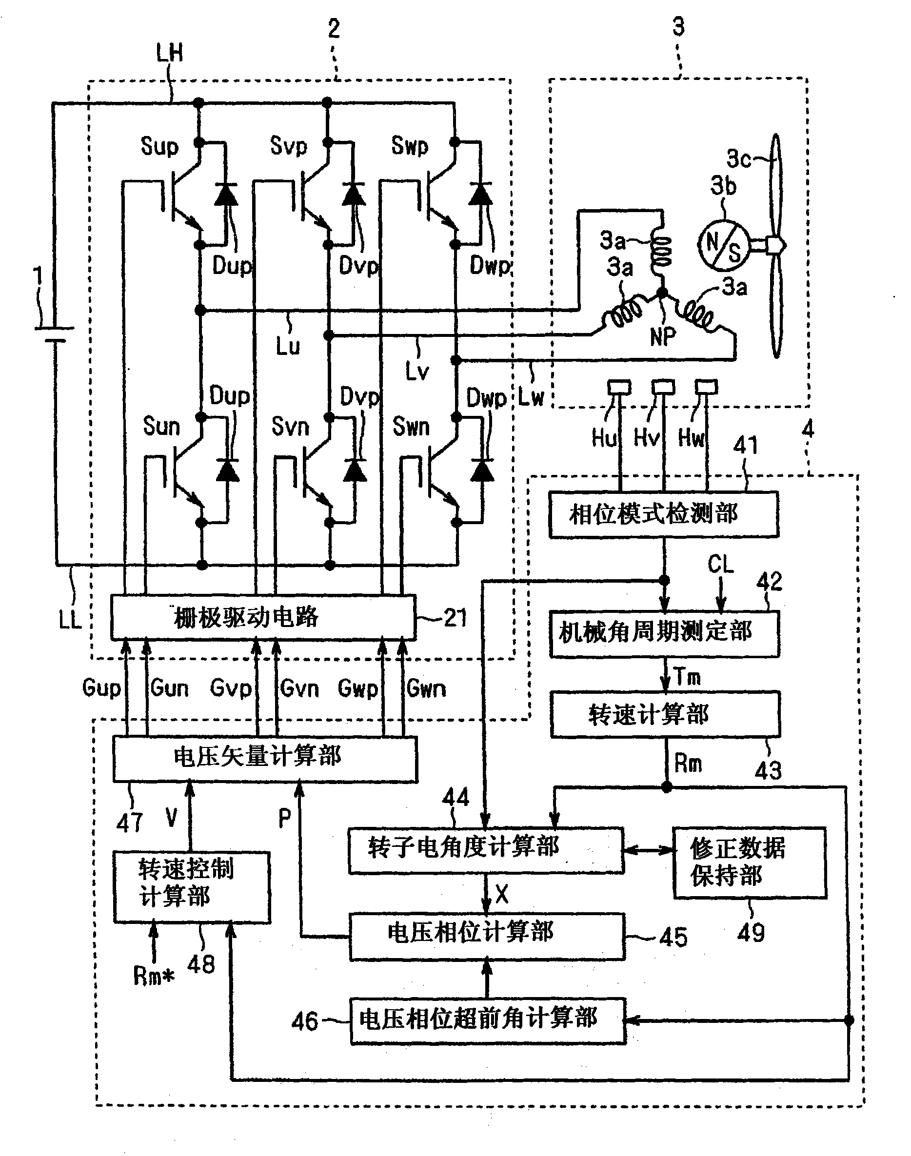
[0033] figure 1 An example of the conceptual configuration of the motor control device is shown. The motor control device includes a DC power supply 1 , an inverter 2 , a gate drive circuit (a grid drive circuit) 21 , a motor 3 , position detection sensors Hu, Hv, and Hw, and a control unit 4 . The control unit 4 includes: a phase pattern detection unit 41, a mechanical angle period measurement unit 42, a rotational speed calculation unit 43, a rotor electrical angle calculation unit 44, a voltage phase calculation unit 45, a voltage phase lead angle calculation unit 46, a voltage vector calculation unit 47, A rotational speed control calculation unit 48 and a correction data storage unit 49 .

[0034] The DC power supply 1 applies a DC voltage Vdc between the DC power supply lines LH, LL.

[0035] The inverter 2 includes an upper arm (high arm) side switching element Sxp (where x represents u, v, and w; hereinafter, the same applies), a lower arm (high arm) side switching e...

no. 2 Embodiment approach

[0102] In the first embodiment, a fan motor including a fan 3 c was exemplified as the motor 3 . In the second embodiment, another product incorporating the motor control device described in the first embodiment will be described. However, the motor does not include the fan 3c.

[0103] Figure 7 It is a figure which shows an example of the conceptual structure of a compressor. The compressor 50 includes a motor drive unit 10 , a compression mechanism 51 , a suction pipe 52 , a discharge pipe 53 , and a shaft 54 ​​. The compressor 50 is mounted, for example, on an air conditioner.

[0104] The motor drive device 10 is the motor drive device described in the first embodiment (only the motor 3 has no fan).

[0105] The compression mechanism 51 is driven by the motor drive 10 via a shaft 54 ​​. The compression mechanism 51 has a compression chamber 55 . The volume of the compression chamber 55 is reduced by the rotation of the motor 3 . The compression chamber 55 connects ...


PUM


Abstract

Provided is a motor control device which can stabilize the rpm. When a rotor (3b) is positioned at one of K predetermined electric angles such as 60 degrees, 180 degrees, and 300 degrees, a voltage vector supplied to a motor (3) is modified upon detection by a position detection sensor. When the rpm exceeds a predetermined value, the number of the predetermined angles is modified to M such as 1 (60 degrees).

Description

technical field [0001] The present invention relates to a motor control method, a motor control device, a fan device, a compressor, and a pump device, and particularly relates to a method for controlling the motor by detecting the position of a rotor of the motor. Background technique [0002] Patent Document 1 describes a method of controlling a motor. The motor control device includes a motor having a rotor, an inverter for supplying a voltage vector to the motor, and a position detection sensor for detecting the position of the rotor. [0003] The position detection sensor detects, for example, electrical angles of 60°, 180°, and 300°, and updates the voltage vector supplied to the motor in response to timings when these electrical angles are detected. [0004] Patent Document 1: (Japanese) Unexamined Patent Publication No. 2001-268963 [0005] The position signal deviates due to the installation deviation of the position detection sensor. In the technology described i...

Claims


Application Information

Patent Timeline
Patent Type & Authority Applications(China)
IPC IPC(8): H02P6/06H02P6/08H02P6/17
CPCH02P6/16H02P6/06
Inventor 前田浩仁池田基伸八木达嶋谷圭介桥本雅文
Owner DAIKIN IND LTD
Why Eureka
Try Eureka