High-pressure oil rail with novel structure

An oil rail, high-pressure technology, applied in engine components, machines/engines, charging systems, etc., can solve problems such as increasing the development cost of parts and components, resource management costs of parts, inconvenient disassembly for inspection and maintenance, and complex engine structure. , to achieve the effect of reducing development and management costs, facilitating maintenance and maintenance, and reducing economic burden

Inactive Publication Date: 2012-01-04
BRITISH JOINT VENTURE PERKINS ENGINES TIANJIN
View PDF0 Cites 1 Cited by
  • Summary
  • Abstract
  • Description
  • Claims
  • Application Information

AI Technical Summary

Problems solved by technology

[0002] At present, with the rapid development of the engine industry and increasingly stringent emission standards, it has become a general trend to choose electronically controlled high-pressure common rail technology to meet high emission requirements. Due to the increase in the electronic control system and related emission auxiliary components, the engine structure is becoming more and more It is complex and the volume is getting bigger and bigger, so reducing the types of engine parts and making the engine easy to install and compact has become a major problem to be solved; practice has proved that most of the existing high-pressure fuel rail systems used by manufacturers are split (i.e. Engines with different numbers of cylinders have separate high-pressure oil rails, and the structural disadvantages are relatively large), which unnecessarily increases the cost of component development and the management of component resources. At the same time, the fuel rail is arranged inside the engine. It is extremely inconvenient, increases assembly man-hours, reduces labor efficiency, and also has the disadvantages of inconvenient disassembly for inspection and maintenance.

Method used


Image

  • High-pressure oil rail with novel structure
  • High-pressure oil rail with novel structure
  • High-pressure oil rail with novel structure

Examples


Embodiment Construction

[0014] In order to further understand the invention content, characteristics and effects of the present invention, the following examples are given, and detailed descriptions are as follows in conjunction with the accompanying drawings:

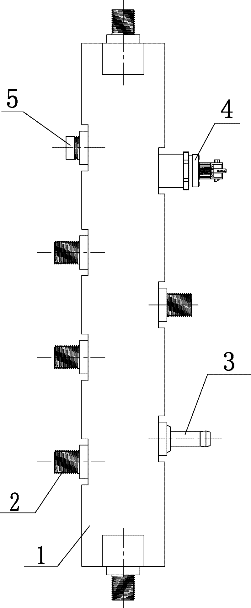
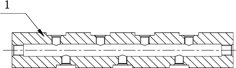
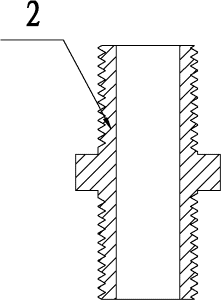
[0015] see Figure 1 to Figure 4 , a high-pressure oil rail, including an oil rail body 1; an oil outlet joint 2, an oil return joint 3 and an oil pressure sensor seat 4 installed on the oil rail body 1; interface, the interfaces on both sides are distributed in a staggered manner, the oil return joint 3 and the oil pressure sensor seat 4 are installed on the two interfaces on the side wall of the oil rail body, and the oil outlet joint 2 and the plugging member 5 are installed on the other interfaces. Both ends of the oil rail body are also provided with interfaces for installing oil outlet joints. In the above structure, the oil outlet joint 2, the oil return joint 3, and the oil pressure sensor seat 4 are all threaded to the oil rail body ...


PUM


Abstract

The invention relates to a high-pressure oil rail, which comprises an oil rail body and an oil outlet joint, an oil return joint and an oil pressure sensor seat mounted on the oil rail body, and the high-pressure oil rail is characterized in that a plurality of interfaces are uniformly distributed on the side wall on the oil rail body, the interfaces on two sides are in crisscross distribution, the oil return joint and the oil pressure sensor seat are mounted on the two interfaces on the side wall of the oil rail body, the oil outlet joint and a sealing and blocking part are mounted on other interfaces, and the interfaces for mounting oil port joints are arranged at two end parts of the oil rail body. The high-pressure oil rail can realize the share of the same high-pressure oil rail among engines with different numbers of cylinders and flexibly select the number and the positions of the oil outlet joints according to the different number of the cylinders of the engines; the high-pressure oil rail is convenient to process, easy to mount and strong in universality; the oil rail body, the oil outlet joint and the like adopt the threaded fitting and mounting structures, thereby realizing quick mounting, shortening the working time, greatly improving the labor efficiency, simultaneously being convenient to detach, and being convenient to repair and maintain; and the engines with the different number of the cylinders can use the unified high-pressure oil rail, thereby facilitating the management of part resources.

Description

technical field [0001] The invention belongs to the technical field of engine manufacture, and in particular relates to a high-pressure oil rail suitable for high emission requirements. Background technique [0002] At present, with the rapid development of the engine industry and increasingly stringent emission standards, it has become a general trend to choose electronically controlled high-pressure common rail technology to meet high emission requirements. Due to the increase in the electronic control system and related emission auxiliary components, the engine structure is becoming more and more It is complex and the volume is getting bigger and bigger, so reducing the types of engine parts and making the engine easy to install and compact has become a major problem to be solved; practice has proved that most of the existing high-pressure fuel rail systems used by manufacturers are split (i.e. Engines with different numbers of cylinders have separate high-pressure oil ra...

Claims


Application Information

Patent Timeline
Patent Type & Authority Patents(China)
IPC IPC(8): F02M55/02
Inventor 金刚郭强郄天才唐飞
Owner BRITISH JOINT VENTURE PERKINS ENGINES TIANJIN
Why Eureka
Try Eureka