Electromechanical coupling transmission device of crawler

A transmission device, electromechanical coupling technology, applied in control devices, vehicle components, transportation and packaging, etc., can solve problems such as reducing the power requirements of traction motors, increasing the difficulty of motor development, increasing the axial size of the system, and reducing development risks. , Conducive to reasonable matching, simple and compact structure

Active Publication Date: 2011-03-16
CHINA NORTH VEHICLE RES INST
View PDF5 Cites 42 Cited by
  • Summary
  • Abstract
  • Description
  • Claims
  • Application Information

AI Technical Summary

Problems solved by technology

[0003] The structure of the double-sided motors is relatively simple. When driving in a straight line, it is realized by driving the left and right driving wheels by the main motor, while in the steering process, it is realized by controlling the speed difference generated by the left and right traction motors, in order to meet the power requirements when turning. requirements, the traction motor must have a large power, therefore, this scheme has high requirements on the motor, which increases the difficulty of motor development; the horizontal axis structure uses the main shaft, zero axis and converging planetary row to solve the steering problem of tracked vehicles. The problem of time-consuming power circulation greatly reduces the power requirements of the traction motor, but the disadvantage is that the direct drive motor, the steering motor and the transmission mechanism are arranged side by side, which increases the axial size of the system and is not conducive to the layout of the system in the vehicle

Method used


Image

  • Electromechanical coupling transmission device of crawler
  • Electromechanical coupling transmission device of crawler
  • Electromechanical coupling transmission device of crawler

Examples


Embodiment Construction

[0047] A control method for an electromechanical coupling transmission device of a crawler vehicle provided by the present invention will be described in more detail below in conjunction with the accompanying drawings and specific embodiments.

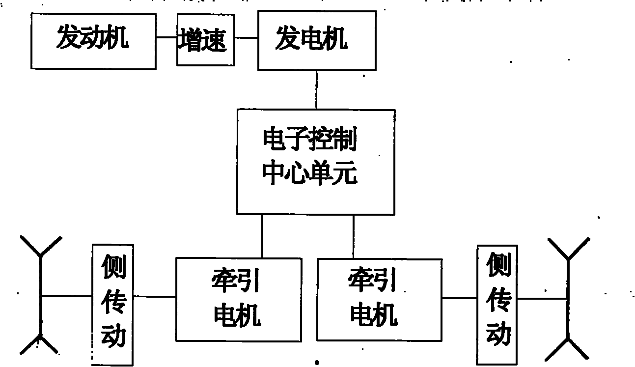
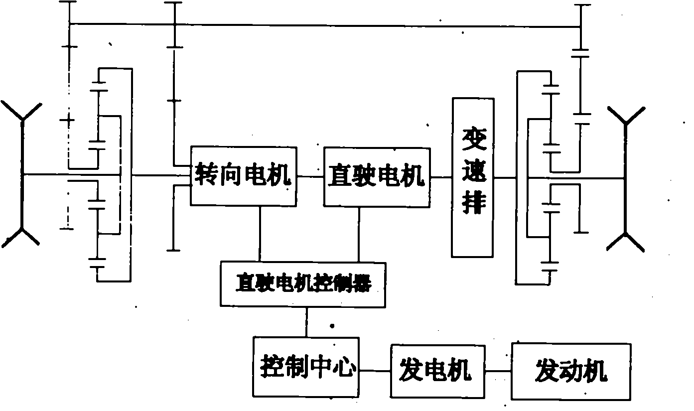
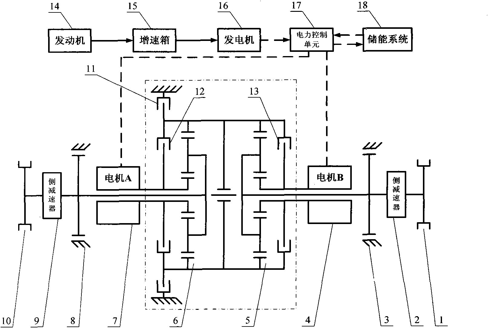
[0048] like figure 1 Shown in the dotted line box is the key of the new electromechanical coupling transmission device of this embodiment - the basic type of power coupling and speed change mechanism structure. On this basis, the steering power coupling can be realized by appropriately adding planetary rows and corresponding control elements. And multi-gear speed change mechanism, in the present embodiment the planet row is two rows.

[0049] (1) Climbing: the brake L-11 is closed, the brake B-3 and the brake A-8 are disconnected, the clutch C1-12 and the clutch C2-13 are disconnected, and the power from the engine 14 is transmitted to the generator through the gearbox 15 16 is converted into electric power, and this electric power i...


PUM


Abstract

The invention relates to an electromechanical coupling transmission device of a crawler. The device comprises an engine, a power coupling and gear shifting mechanism, two motors, a power control unit and an energy storage system, wherein the two motors are connected with sun gears of two planet rows of the power coupling and gear shifting mechanism respectively, a gear ring of the two planet rowsof the power coupling and gear shifting mechanism is shared, a clutch is arranged between the two sun gears and the shared gear ring, and the shared gear ring is provided with a brake and output through a planet carrier. The transmission device removes a steering gear set and a zero shaft of double-flow transmission of the crawler, and has flexible allocation, capability of making full use of space and compact structure. Because of the power coupling and gear shifting mechanism, the requirement for the motors is reduced, and the research and manufacture risks of the motors are reduced.

Description

[technical field] [0001] The present invention relates to transmissions and, in particular, to electromechanical coupling transmissions. [Background technique] [0002] At present, the electric transmission device of tracked vehicles is mainly a double-sided motor structure and a transverse shaft structure. like image 3 It is a double-sided motor structure, such as Figure 4 It is a horizontal axis structure. [0003] The structure of the double-sided motors is relatively simple. When driving in a straight line, it is realized by driving the left and right driving wheels by the main motor, while in the steering process, it is realized by controlling the speed difference generated by the left and right traction motors, in order to meet the power requirements when turning. requirements, the traction motor must have a large power, therefore, this scheme has high requirements on the motor, which increases the difficulty of motor development; the horizontal axis structure ...

Claims


Application Information

Patent Timeline
Patent Type & Authority Applications(China)
IPC IPC(8): B60K17/12B60K17/28
Inventor 盖江涛周广明马田马晓枫万帆白宫鼎马长军孙占春张欣
Owner CHINA NORTH VEHICLE RES INST
Why Eureka
Try Eureka